6
II. Operation
Thermostat
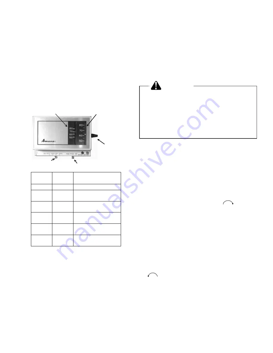
There are many types and styles of thermostats but the
operation is usually similar. BE SURE TO BECOME FAMIL-
IAR WITH YOUR THERMOSTAT. The simplest type of
thermostat only starts and stops the furnace to maintain the
proper room temperature. The most widely used types will
control both heating and cooling functions and will have a Fan
Switch with Auto and ON settings. On Auto, the Circulating
Air Blower will cycle on/off with the furnace but if switched to
ON it will run constantly whether or not the furnace is on.
In addition there are thermostats that automatically switch
from Heating to Cooling and with night setbacks. The night
set-back, or multiple set-back type, will lower the tempera-
ture at night or during the day when no one is at home.
Cool/Heat
Switch
Fan
Switch
Cool/Heat
Temperature
Control Dial
Room Temperature
Thermostat
Thermostat
Control
Lever
System
Switch
Fan
Switch
Action
OFF
AUTO
None
COOL
AUTO
System only cools, fan
cycles off and on.
COOL
ON
System only cools, fan
runs all the time.
HEAT
AUTO
System only heats, fan
cycles off and on.
HEAT
ON
System only heats, fan
runs all the time.
OFF
ON
No heating or cooling,
fan runs all the time.
Figure 2
Typical Thermostat
Electrical Components
This furnace is equipped with an electronic ignition device
which lights the burners. It also has a power vent blower to
exhaust combustion products.
Keep both doors in place except for inspection and mainte-
nance. An interlock switch prevents furnace operation if the
blower door is not in place.
Do not use this furnace if any part has been under water.
Immediately call a qualified servicer to inspect the furnace
and to replace any part of the control system and any gas
control which has been under water.
WARNING
PERSONAL INJURY HAZARD
To avoid death, personal injury or property
damage do not remove any internal com-
partment covers. Electrical components are
contained in both compartments. Contact a
qualified servicer at once if an abnormal
condition is noticed.
Operating Instructions
1. Close the manual gas valve external to the furnace.
2. Turn off the electrical power supply to the furnace.
3. Set room thermostat to lowest possible setting.
4. Remove the upper door on the front of the furnace by
turning the latch screw 1/4 turn.
5. This furnace is equipped with an ignition device which
automatically lights the burner. Do not try to light burner
by hand.
6. Turn the gas control knob clockwise
to the OFF
position for either the White Rodgers 36-E gas valve
(Figure 3) or the Honeywell VR-8205 gas valve (Figure
4). For the Robertshaw 7222 gas valve (Figure 5) slide
the lever to the "OFF" position. Do not use excessive
force.
7. Wait five minutes to clear out any gas. Then smell for
gas, including near the floor. This is important , because
some types of gas are heavier than air.
8. If you smell gas following the five minute waiting period
in Step 7, immediately follow the instructions on the
cover of this manual. If you do not smell gas after five
minutes, turn the gas control knob counterclockwise
to the ON position for either the White Rodgers 36-
E gas valve (Figure 3) or the Honeywell VR-8205 gas
valve (Figure 4). For the Robertshaw 7222 gas valve
(Figure 5) slide the lever to the "ON" position. Do not use
excessive force.
9. Replace the door on the front of the furnace.
10. Open the manual gas valve external to the furnace.
11. Turn on the electrical power supply to the furnace.
12. Set thermostat to desired setting.


