background image

3

GENERAL INFORMATION 

WARNING

To prevent property damage, personal injury 

or death, due to fire, explosions, smoke, 

soot, condensation, electric shock or carbon 

monoxide, this unit must be properly installed, 

repaired, operated, and maintained. 

This unit is approved for outdoor installation ONLY

Rated performance is achieved after 20 hours of operation. 

Rated performance is delivered at the specified airflow.  

See product specification sheet for packaged models. 

Specification sheets can be found at 


www.amana-hac.com  for Amana brand products. Within 

the website, please select the products menu and then 

select the submenu for the type of product to be installed, 

such as air conditioners or heat pumps, to access a list 

of product pages that each contain links to that model’s 

specification sheet.

To assure that your unit operates safely and efficiently, it 

must be installed, operated, and maintained in accordance 

with these installation and operating instructions, all local 

building codes and ordinances.

EPA Regulations

Important: The United States Environmental 

Protection Agency (EPA) has issued various 

regulations regarding the introduction and 

disposal of refrigerants in this unit. Failure 

to follow these regulations may harm the 

environment and can lead to the imposition 

of substantial fines. Because regulations may 

vary due to passage of new laws, we suggest a 

certified technician perform any work done on 

this unit. Should you have any questions please 

contact the local office of the EPA.

National Codes

This product is designed and manufactured to permit  

installation in accordance with National Codes. It is the 

installer’s responsibility to install the product in accordance 

with National Codes and/or prevailing local codes and 

regulations.

The heating and cooling capacities of the unit should be 

greater than or equal to the design heating and cooling 

loads of the area to be conditioned. The loads should be 

calculated by an approved method or in accordance with 

ASHRAE Guide or Manual J - Load Calculations published 

by the Air Conditioning Contractors of America.

Obtain from:

American National Standards Institute 

www.ansi.org

System design and installation should also, where 

applicable, follow information presented in accepted 

industry guides such as the ASHRAE Handbooks. The 

manufacturer assumes no responsibility for equipment 

installed in violation of any code or regulation. The 

mechanical installation of the packaged roof top units 

consists of making final connections between the unit and 

building services; supply and return duct connections; and 

drain connections (if required).  The internal systems of 

the unit are completely factory-installed and tested prior to 

shipment.

Units are generally installed on a steel roof mounting 

curb assembly which has been shipped to the job site for 

installation on the roof structure prior to the arrival of the 

unit.  The model number shown on the unit’s identification 

plate identifies the various components of the unit such as 

refrigeration tonnage, heating output and voltage.

Carefully inspect the unit for damage including damage 

to the cabinetry.  Any bolts or screws which may have 

loosened in transit must be re-tightened.  

In the event of damage, the receiver should:

1.  Make notation on delivery receipt of any visible 

damage to shipment or container.

2.  Notify carrier promptly and request an inspection.

3.  In case of concealed damage, carrier should be 

notified as soon as possible-preferably within 5 days.

4.  File the claim with the following supporting 

documents:

a. 

Original Bill of Lading, certified copy, or 

indemnity bond.

b.  Original paid freight bill or indemnity in lieu 

thereof. 

c. 

Original invoice or certified copy thereof, 

showing trade and other discounts or 

reductions.

d.  Copy of the inspection report issued by carrier 

representative at the time damage is reported 

to the carrier. The carrier is responsible for 

making prompt inspection of damage and for 

a thorough investigation of each claim. The 

distributor or manufacturer will not accept 

claims from dealers for transportation damage.

NOTE: When inspecting the unit for 

transportation damage, remove all packaging 

materials. Recycle or dispose  of the packaging 

material according to local codes.

Pre-Installation Checks

Carefully read all instructions for the installation prior 

to installing unit. Ensure each step or procedure is 

understood and any special considerations are taken into 

account before starting installation.  Assemble all tools, 

hardware and supplies needed to complete the installation. 

Some items may need to be purchased locally.

Summary of Contents for M Series

Page 1: ...g to install adjust service or repair the equipment specified in this manual without proper training may result in product damage property damage personal injury or death WARNING INDEX ReplacementParts 2 Safety Instructions 2 GeneralInformation 3 Unit Location 4 Clearances 5 Roof Curb Post Installation Checks 5 Roof Top Duct Connections 5 RiggingDetails 6 Electrical Wiring 7 Circulating Air And Fi...

Page 2: ...e place for future reference CAUTION Sheet metal parts screws clips and similar items inherently have sharp edges and it is necessary that the installer and service personnel exercise caution WARNING Do not connect to or use any device that is not design certified by daikin for use with this unit Serious property damage personal injury reduced unit performance and or hazardous conditions may resul...

Page 3: ...here applicable follow information presented in accepted industry guides such as the ASHRAE Handbooks The manufacturer assumes no responsibility for equipment installed in violation of any code or regulation The mechanical installation of the packaged roof top units consists of making final connections between the unit and building services supply and return duct connections and drain connections ...

Page 4: ... Installations Only To avoid possible property damage or personal injury the roof must have sufficient structural strength to carry the weight of the unit s and snow or water loads as required by local codes Consult a structural engineer to determine the weight capabilities of the roof The unit may be installed directly on wood floors or on Class A Class B or Class C roof covering material To avoi...

Page 5: ...CES Unit Clearances In situations that have multiple units a 36 minimum clearance is required between the condenser coils Adequate clearance around the unit should be kept for safety service maintenance and proper unit operation A clearance of 48 is recommended on all sides of the unit to facilitate possible parts replacement to allow service access and to insure proper ventilation and condenser a...

Page 6: ...h the following bullet points must be observed when installing the unit Unit must be lifted by the four lifting holes located at the base frame corners Lifting cables should be attached to the unit with shackles The distance between the crane hook and the top of the unit must not be less than 60 Two spreader bars must span over the unit to prevent damage to the cabinet by the lift cables Spreader ...

Page 7: ... present Failure to do so may cause property damage personal injury or death WARNING HIGH VOLTAGE To avoid personal injury or death due to electrical shock do not tamper with factory wiring The interanl power and control wiring of these units are factory installed and have been thoroughly tested prior to shipment Contact your local representative if assistance is required CAUTION Conduit and fitti...

Page 8: ...ovided for this purpose Do not use the ground lug for connecting a neutral conductor Connect power wiring to the electrical power block located within the main control box Control Box control box Connections note depending on the options installed the location of the components may vary in some models WARNING Failure of unit due to operation on improper line voltage or with excessive phase unbalan...

Page 9: ...ILTERS Ductwork The supply duct from the unit through a wall may be installed without clearance However minimum unit clearances must be maintained see Clearances section The supply duct should be provided with an access panel large enough to inspect the air chamber downstream of the heat exchanger A cover should be tightly attached to prevent air leaks Ductwork dimensions are shown in the roof cur...

Page 10: ...are not covered under the warranty After the machines are used for temporary heating or cooling inspect the coils fans and motors for unacceptable levels of construction dust and dirt and install new filters Contractor Responsibility The installing contractor must be certain that All supply and return air ductwork is in place properly sealed and corresponds with installation instructions All therm...

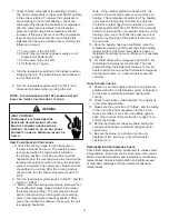
Page 11: ...er speed setting than the G Y1 and W1 speed setting If Electric Heater kit is installed use the red wire provided with the literature kit to jumper terminal TB1 W1 to an unoccupied speed tap that satisfies the minimum airflow required for the heater kit This must be a different tap than Y2 is connected to Refer to Appendix D for minimum required airflow for electric heaters Note On Heat Pump units...

Page 12: ...running with the reversing valve in the deenergized heating position After giving the unit time to settle out make sure the unit is supplying heated air Note If the outdoor ambient is above 80 F the unit may trip on its high pressure cut out when on heating The compressor should stop The heating cycle must be thoroughly checked so postpone the test to another day when conditions are more suitable ...

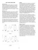
Page 13: ... to provide supplementary heat for all heat pump installations in areas where the temperature drops below 45 F It is also a good practice to provide sufficient supplementary heat to handle the entire heating requirement should there be a component failure of the heat pump such as a compressor or refrigerant leak etc Since the temperature of the refrigerant in the outdoor coil on the heating cycle ...

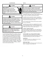
Page 14: ...fficiency or equipment damage due to dust and lint build up on internal parts never operate unit without an air filter installed in the return air system Every application may require a different frequency of replacement of dirty filters Filters must be replaced at least every three 3 months during operating seasons Dirty filters are the most common cause of inadequate heating or cooling performan...

Page 15: ...15 Wiring Example Electric Heat Wiring Example ...

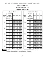
Page 16: ...80 0 8 1960 1045 0 86 0 2 2189 902 0 81 0 2 2234 960 0 86 0 4 2119 943 0 84 0 4 2162 1003 0 90 0 6 2059 979 0 88 0 6 2101 1042 0 93 0 8 2012 1009 0 90 0 8 2053 1073 0 96 0 2 2254 923 0 88 0 2 2300 982 0 93 0 4 2178 964 0 92 0 4 2222 1025 0 98 0 6 2127 997 0 95 0 6 2170 1061 1 01 0 8 2078 1029 0 98 0 8 2120 1095 1 04 Shaded area indicates air flow below 1500 SCFM 300 SCFM ton that is not recommende...

Page 17: ...25 7 2 6 5 119 129 125 150 134 148 150 150 7 2 6 5 142 155 150 175 Power Supply Model Number Electrical Rating Compressor Outdoor Fan Motor Indoor Fan Motor Optional Electric Heat Optional Powered Convienience Outlet FLA Optional Power Exhaust FLA 6 9 1 0 3 3 5 Direct Drive Standard Static 1 APH1660M 208 230 1 60 1 26 9 152 9 EH 1S15 11 3 15 0 54 2 62 5 EH 1S20 15 0 20 0 72 2 83 3 EH 1S05 3 76 5 0...

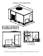
Page 18: ...URB LOCATION EMBOSS FOR THRU THE BASE UTILITIES RETURN 11 X 25 SUPPLY 12 X 17 Horizontal Discharge Vertical Discharge NOTE Refer to IOD 7082 included in the literature pack for installing horizontal duct covers 48 5 16 74 A 47 5 8 73 3 8 5 6 3 16 7 3 8 SUPPLY 12 X 17 RETURN 11 X 25 Model Dim A 5 Ton Heat Pump 43 1 2 ...

Page 19: ...Electric Heater Heater Type X Staged S SCR modulating Voltage 1 208 230 1 60 Single phase 60 Hz Chassis S Small Kilowatt 5 5 kW 10 10 kW 15 15 kW 18 18 KW 20 20 kW 30 30 kW EH S05 5 1500 EH S10 10 1500 EH S15 15 1500 EH S20 20 1550 2500 MAXIMUM SCFM UNIT HEATER KIT MODEL NUMBER APH1660M kW MINIMUM SCFM ...

Page 20: ...CE INSTALLED NOTES 4 3 2 1 5 6 BLACK BLUE BLUE WITH PINK STRIPE BROWN GREEN GRAY ORANGE PINK PURPLE RED TAN WHITE YELLOW YELLOW WITH PINK STRIPE BK BL BL PK BR GR GY OR PK PU RD TN WH YL YL PK HIGH VOLTAGE LOW VOLTAGE OPTIONAL HIGH VOLTAGE OPTIONAL LOW VOLTAGE CHASSIS GROUND FIELD WIRING FACTORY WIRING HIGH VOLTAGE LOW VOLTAGE EARTH GROUND COMPONENT LEGEND 12 11 10 9 8 7 6 5 4 3 2 1 12 11 10 9 8 7...

Page 21: ...21 ...

Page 22: ...22 ...

Page 23: ...23 THIS PAGE IS INTENTIONALLY LEFT BLANK ...

Page 24: ...he QR code on the right for the product brand you purchased to be directed to the feedback page GOODMAN BRAND AMANA BRAND GOODMAN BRAND AMANA BRAND PRODUCT REGISTRATION Thank you for your recent purchase Though not required to get the protection of the standard warranty registering your product is a relatively short process and entitles you to additional warranty protection except that failure by ...

Reviews: