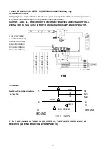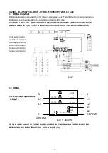
3.1 WIRING DIAGRAM
Wiring diagrams are provided here for reference purposes only. This information is also provided on
schematics attached directly to the appliance on the top left corner.
CAUTION: LABEL ALL WIRES PRIOR TO DISCONNECTION WHEN SERVICING CONTROLS.
WIRING ERRORS CAN CAUSE IMPROPER AND DANGEROUS APPLIANCE OPERATION.
L1=BLACK(POWER)
L2=ORANGE(POWER)
G=GREEN(GROUND)
N=WHITE(COMMON)
N1=BLUE(COMMON)
N2=BLUE(COMMON)
3.2 WIRING
See Power Supply Specifications
on Page 14.
IF THE APPLIANCE IS TO BE HARD WIRED IN, THE POWER CORD MUST BE
REMOVED (SEE INSTRUCTION #1 ON PAGE 20)
3. 240V, BI-50/60/72/88-DEEP-XT (DE-T190050/60/72/88-01) only
21
N
L1
L2
G
GROUND
120 VAC
120 VAC
N
L1
L2
GROUND
N1
N2
BLACK
WHITE
ORANGE
BLUE
BLUE
YELLOW AND GREEN
240 V 3000W


