background image

01

02

03

04

05

06

07

08

09

10

11

12

13

14

15

16

17

18

19

20

21

22

23

24

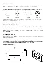
PLUG INSTALLATION

UNPACKING AND TESTING APPLIANCE

LOCATING THE FIREPLACE

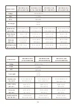
PRODUCT SPECIFICATION

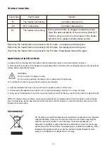
Hold the male plug and insert it into the female receptacle. The receptacle is locate on the left side if the fireplace. 

Please make sure the plugs are firmly connected.

Carefully remove the appliance from the box.
Prior to installing the appliance, test to make sure the appliance operates properly by plugging the power supply cord 

into a 240 Volt grounded outlet.
Test all aspects of its operation (manual switches, remote and heater) to make sure all components are operating 

correctly.

NOTE: There may be trace of odor during the first few minutes of initial use. This is harmless, normal and will 

never occur again.

Plan where to locate and frame the fireplace. This will save time and money later when you install the fireplace. Before 

installation consider the following:
1. Where the fireplace is located must allow for wall and ceiling clearances

2. Consider a location where the fireplace screen will not be exposed to direct sunlight from windows or doors.
3.  A 15 ampere, 240 Volt, 50-60 Hz branch circuit with proper ground must be available at the location. Preferably a 

dedicated branch circuit should be provided to avoid circuit breakers to trip of fuses to blow.

W3

H3

D3

W2

D

H2 H1

H

W1

W

Your power cord will come separate from the unit, please locate it when unpacking your fireplace. The plug contained 

inside the box is predetermined at the factory and according to orders placed by authorized dealers.

Available are UK, European, Swiss & Australian plugs. Should you require any of these options please contact your 

dealer for purchase. You will be required to give them the correct part number as listed below.


European plug

10103030E

Swiss plug

10103109E

UK plug

10103060E

Australian plug

10103087F

Summary of Contents for BS1900034-1/EU4

Page 1: ...is are known to the State of California to cause birth defects of other reproductive harm For more information visit www p65warnings ca gov SAFETY INFORMATION Do not store or use gasoline or other fla...

Page 2: ...Electric Fireplace IMPORTANT INSTRUCTIONS 03 CAUTIONS 04 PLUG INSTALLATION 05 UNPACKING AND TESTING APPLIANCE 05 LOCATING THE FIREPLACE 05 PRODUCT SPECIFICATION 05 INSTALLATION WALL MOUNT 07 INSTALLA...

Page 3: ...not use this heater with a programmer timer separate remote control system or any other device that switches the heater on automatically since a fire risk exists if the heater is covered or positioned...

Page 4: ...nt it from being tipped over Always use a fireguard when young children and infirm persons can come into contact with the heater Never leave children unsupervised in a room where the heater is ON and...

Page 5: ...u install the fireplace Before installation consider the following 1 Where the fireplace is located must allow for wall and ceiling clearances 2 Consider a location where the fireplace screen will not...

Page 6: ...cm 90 1 4 x 16 7 8 229 3 x 43 cm 32 3 8 x 15 5 8 x 5 1 2 82 3 x 39 6 x 14 cm 42 1 4 x 15 5 8 x 5 1 2 107 2 x 39 6 x 14 cm 50 1 4 x 15 5 8 x 5 1 2 127 6 x 39 6 x 14 cm 60 1 4 x 15 5 8 x 5 1 2 153 x 39...

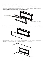
Page 7: ...wiring pipe wires etc in the area to be drilled Drill 6 or more holes depending on the size of he unit purchased using a suitable size drill bit and insert the wall plugs into the holes 4 Remove the h...

Page 8: ...ll with a framed opening to accommodate the size of your unit Leave at least 1 4 6mm around the edge of the applicnce Any new wiring must be done in compliance with local and national codes and other...

Page 9: ...well and there is no gap between the trim and the wall after installation 6 Remove the trim following STEP 1 Screw back the inner side steel panels 7 Insert the front glass panel back in place after t...

Page 10: ...cated here Screws Located Here 2 Carefully remove the front glass panel once the trim has been removed Use caution as the glass is now loose 3 Pour the media into the tray Feel free to use any combina...

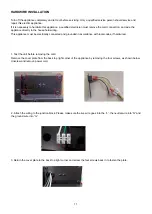
Page 11: ...s appliance must be electrically connected and grounded in accordance with local codes if hardwired 1 Test the unit before removing the cord Remove the cover plate from the back top right corner of th...

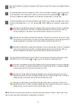
Page 12: ...ing press the button again to clear the current timing If the timing in off position the second press will show 30 Multiple times to set operating duration to OF 30 min 1h 2h 3h 4h 5h 6h 7h 8h Press a...

Page 13: ...7 30 8 00 Once you have set the timer The icon will be displayed on the LCD screen of the remote control Press this button again cancel the timing setting and the icon disappears When the timer is up...

Page 14: ...ssed the brightness of the blue color decrease There are 7 brightness levels 8 2 dynamic level 1 and OFF no display settings that can be cycled through When no number is displayed on the remote contro...

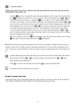
Page 15: ...LCD screen of the remote control The digital temperature flashes at this time you can set the desired temperature with or keys The fireplace will beep to acknowledge the settings Now the 7 day functi...

Page 16: ...als such as detergents and abrasives Do not allow the interior to get wet as this could create a hazard Light accumulated dust may be removed from the appliance with a soft dry cloth To store away the...

Page 17: ...N PART NUMBER 30002180 3000181230001859 3000185930001961 3000196130001859 74 30002056 30002059 30002059 74 60000190 60000196 60000192 60000191 30002010 10002255P 60000198 60000197 60000199 60000201 60...

Page 18: ...18 EXPLODED VIEW...

Page 19: ...19...

Page 20: ...20...

Reviews: