background image


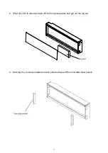
4.  Put the trim back onto the appliance and fasten with screws.(NOTE: This step is to make 

sure that the fireplace fits the wall opening

the wall after installation) 


5.  Put the fireplace into the wall opening and fix it to the wall by screwing 2 screws each 

side.  


18

Put the trim back onto the appliance and fasten with screws.(NOTE: This step is to make 

sure that the fireplace fits the wall opening well and there is no gap between the trim and 

Put the fireplace into the wall opening and fix it to the wall by screwing 2 screws each 

Put the trim back onto the appliance and fasten with screws.(NOTE: This step is to make 

well and there is no gap between the trim and 

Put the fireplace into the wall opening and fix it to the wall by screwing 2 screws each 

Summary of Contents for SM-1900100-1

Page 1: ...NCE CONSUMER RETAIN THIS MANUAL FOR FUTURE REFERENCE INSTALLER LEAVE THIS MANUAL WITH THE APPLIANCE CONSUMER RETAIN THIS MANUAL FOR FUTURE REFERENCE SYM 34 SM 190034 1 SYM 42 SM 190042 1 SYM 50 SM 190050 1 SYM 60 SM 190060 1 SYM 74 SM 190074 1 SYM 88 SM 190088 1 SYM 100 SM 1900100 1 INSTALLATION OWNER S MANUAL SYMMETRY SERIES Version 202201 ...

Page 2: ... APPLIANCE 5 LOCATING THE FIREPLACE 5 SYM 34 SM 190034 1 6 SYM 42 SM 190042 1 7 SYM 50 SM 190050 1 8 SYM 60 SM 190060 1 9 SYM 74 SM 190074 1 10 SYM 88 SM 190088 1 11 SYM 100 SM 1900100 1 12 MANTEL CLEARANCE 13 FOR BATHROOM USE 13 OUTDOOR INSTALLATION 14 INSTALLATION 15 HARDWIRE INSTALLATION 24 MEDIA OPTIONS 25 DECORATIVE MEDIA INSTALLATION 25 OPERATION 26 MANUAL OPERATION 26 REMOTE CONTROL OPERATI...

Page 3: ...e it will not be tripped over 7 Do not modify this fireplace Use it as described in the manual Any other use not recommended by the manufacture may cause fire shock or injury to persons 8 Do not use this heater with programmer timer separate remote control system or any other device that switches the heater on automatically since a fire risk exists if the heater is covered or positioned incorrectl...

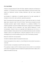
Page 4: ...cy energy and if not installed and used in accordance with the instructions may cause harmful interference to radio communications However there is no guarantee that interference will not occur in a particular installation If this equipment does cause harmful interference to radio or television reception which can be determined by turning the equipment off and on the user is encouraged to try to c...

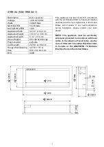
Page 5: ...winter mon fireplace to reach room temperature before turning it on NOTE There may be trace of odor during the first few minutes of initial use This is harmless normal and will never occur again 120 Volts The cord has a plug as shown in A An adapter as shown in C is available for connecting three blade grounding type plugs to two receptacles The green grounding lug extending from the adapter must ...

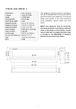
Page 6: ... 6 cm BTU 4095 This appliance has been tested in accordance with the UL Standard 2021 for fixed and location dedicated electric room appliances in the United States and Canada If you need assistance during installation please contact your local dealer NOTE This appliance must be electrically wired and grounded in accordance with local codes In the absence of local codes use the current CSA C22 1 C...

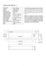
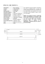
Page 7: ...pliance has been tested in accordance with the UL Standard 2021 for fixed and location dedicated electric room appliances in the United States and Canada If you need assistance during installation please contact your local dealer NOTE This appliance must be electrically wired and grounded in accordance with local codes In the absence of local codes use the current CSA C22 1 Canadian Electrical Cod...

Page 8: ... 128 9 cm 40 6 cm BTU 4095 This appliance has been tested in accordance with the UL Standard 2021 for fixed and location dedicated electric room appliances in the United States and Canada If you need assistance during installation please contact your local dealer NOTE This appliance must be electrically wired and grounded in accordance with local codes In the absence of local codes use the current...

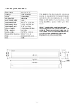
Page 9: ... 154 3 cm 40 6 cm BTU 4095 This appliance has been tested in accordance with the UL Standard 2021 for fixed and location dedicated electric room appliances in the United States and Canada If you need assistance during installation please contact your local dealer NOTE This appliance must be electrically wired and grounded in accordance with local codes In the absence of local codes use the current...

Page 10: ... or 189 9 cm 40 6 cm BTU 4095 This appliance has been tested in accordance with the UL Standard 2021 for fixed and location dedicated electric room appliances in the United States and Canada If you need assistance during installation please contact your local dealer NOTE This appliance must be electrically wired and grounded in accordance with local codes In the absence of local codes use the curr...

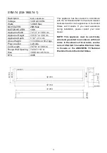
Page 11: ...appliance has been tested in accordance with the UL Standard 2021 for fixed and location dedicated electric room appliances in the United States and Canada If you need assistance during installation please contact your local dealer NOTE This appliance must be electrically wired and grounded in accordance with local codes In the absence of local codes use the current CSA C22 1 Canadian Electrical C...

Page 12: ... appliance has been tested in accordance with the UL Standard 2021 for fixed and location dedicated electric room appliances in the United States and Canada If you need assistance during installation please contact your local dealer NOTE This appliance must be electrically wired and grounded in accordance with local codes In the absence of local codes use the current CSA C22 1 Canadian Electrical ...

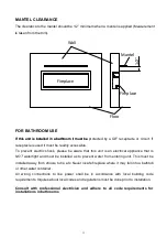
Page 13: ...must be installed as to prevent water from entering unit This must be installed away from shows tubs etc Never locate fireplace where it may fall into a bathtub or other water container All wiring connections to line power shall be in accordance with local building code requirements Inquires about local codes and regulations must be done prior to installation MANTEL CLEARANCE If this unit is insta...

Page 14: ...the listed mantel and combustibles clearances a rain protection overhang factor of 1 2 shall be constructed to the front and to each side of the installed appliance See illustration below All wiring connections to line power shall be in accordance with local building code requirements Inquires about local codes and regulations must be done prior to installation 14 ...

Page 15: ...e 4 WARNING Be sure that the bolts have been fixed firmly enough to withstand the weight 15 WALL MOUNT NOTE Due to the many different materials used to build walls it is highly recommended that you consult your local builder before you install this appliance on a wall Select a location that is not prone to moisture and is located at least 0 91 m or 3 feet away from combustible rtains or drapes fur...

Page 16: ...ith a framed opening to accommodate the size of your unit Leave at least 1 4 6mm around the edge of the appliance Any new wiring must be done in compliance with local and national codes and other applicable regulations Prior to installing test the appliance to make sure the appliance is fully operational by plugging the power supply cord into a 120 Volt grounded outlet The rough wall opening size ...

Page 17: ... steel panels 17 Unscrew the 2 screws located on each side and take off the inner side steel panels Unscrew the 2 screws located on each side and take off the inner side steel panels 2 When the trim is removed take off the front glass panel and get out the log set Log set ...

Page 18: ... back onto the appliance and fasten with screws NOTE This step is to make sure that the fireplace fits the wall opening well and there is no gap between the trim and Put the fireplace into the wall opening and fix it to the wall by screwing 2 screws each Put the trim back onto the appliance and fasten with screws NOTE This step is to make well and there is no gap between the trim and Put the firep...

Page 19: ...rim after you finish the media decoration 19 Remove the trim following STEP 1 Screw back the inner side steel panels Put back the front glass panel and screw back the trim after you finish the media inner side steel panels Put back the front glass panel and screw back the trim after you finish the media ...

Page 20: ...ugh wall opening size of the fireplace in installation from Screw locations Magnetic stone locations Log set 1 Unscrew 4 screws to take off the trim and get out the log set NOTE Keep hold of the front glass as it may fall down automatically when the trim is removed W D H SYM 34 SM 190034 1 32 7 8 4 16 SYM 42 SM 190042 1 42 3 4 4 16 SYM 50 SM 190050 1 50 3 4 4 16 SYM 60 SM 190060 1 60 3 4 4 16 SYM ...

Page 21: ... steel panels 21 Unscrew the 2 screws located on each side and take off the inner side steel panels Unscrew the 2 screws located on each side and take off the inner side steel panels 2 When the trim is removed take off the front glass panel and get out the log set Log set ...

Page 22: ... with screws NOTE This step is to make sure that the fireplace fits the wall opening well and there is no gap between the trim and the wall after installation 5 Put the fireplace into the wall opening and fix it to the wall by screwing 2 screws each side ...

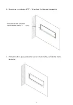
Page 23: ...23 6 Remove the trim following STEP 1 Screw back the inner side steel panels 7 Put back the front glass panel and screw back the trim after you finish the media decoration ...

Page 24: ... block Please make sure the live wire goes into the L the wire into N and the ground wire into G Return the cover plate to the left side and screw the two screws back in to fasten the plate Turn off the appliance completely and let cool before servicing Only a qualified service Remove the cover plate from the left side of the appliance by removing the two screws Attach the wiring to the junction b...

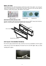
Page 25: ...t back the trim and front glass after you finish any combination of the fire glass media that you find most appealing Put back the trim and front glass after you finish Screw locations Magnetic stone locations Log set Unscrew 4 screws to take off the trim and get out the log set NOTE Keep hold of the front glass as it may fall down automatically when the trim is removed BIRCH LOG SET 25 The media ...

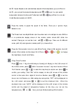
Page 26: ...ght brightness There are 11 brightness levels d11 d2 dynamic condition d1 and the OFF OF setting you can cycle through 4 Press to set the turn off time 30min 1h 2h 3h 4h 5h 6h 7h 8h t0 The indicator light the current timing If the timing in off position the second press will show 30 Multiple times to set operating duration to OF 30 min 1h 2h 3h 4h 5h 6h 7h 8h 5 Press or the first time to display t...

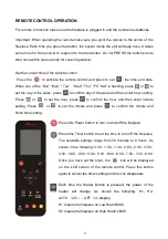
Page 27: ...of the week and then enter hour setting Press or to set the hour press to confirm the hour and then enter minute setting Press or to set the minute and press to confirm the minute and finish time setting Press this Power button to turn on and off the fireplace Press this Timer button to set the time to turn off the fireplace The available settings range from 30 minutes to 8 hours As shown in the f...

Page 28: ...conds to enter 7 day timer function When Sun flashes press or to select the day that you want to set press to confirm your setting Then ON will be display on the LCD screen of the remote control at the same time digital of time hour flashes press or to set the time to turn the fireplace on After setting the startup time OFF will be displayed on the LCD screen and press or to set the shutdown time ...

Page 29: ... da will disappears NOTE If the 7 day timing and the general timing are set at the same time the system will respond to an earlier shutdown time Press Refer button to check the settings of 7 day timer Press or to see the settings of the day of the week and or the settings of the startup and shutdown time y timer and the icon ...

Page 30: ...hone download and install 2 Scan the QR code below with your mobile phone WIFI SETTING AND FIREPLACE OPERATION 1 Create an account and log in 2 When you log in touch FIG 1 to enter in FIG 2 Touch others on the left corner first and then choose Connector Wi fi to enter in FIG 3 to set your Wi fi account and password FIG 1 FIG 2 FIG 3 ...

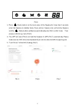
Page 31: ...rom the fireplace and the flame button will flash as well indicating that Wi fi is in EZ mode Then please confirm to go next FIG 5 4 The APP will scan FIG 6 and add the fireplace to APP FIG 7 automatically Please make sure the Wi fi account and password you set are correct and Wi fi signal is good 5 Touch Done to finish Wi fi setting FIG 7 FIG 5 FIG 6 FIG 7 ...

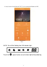
Page 32: ... 6 Now you are in the interface like FIG 7 You can operate the fireplace via Wi fi FIG 7 NOTE Turn off the flashing blue Wifi indicator light Touch the power button once the blue light will stop flashing ...

Page 33: ...4 601137C Qty 4 6 Flame motor 1 1010501 7 Flicker Assembly 1 3200505B 3236505 3237505 3239505 3204505B 3205505B 3206505B 8 Fire Box 1 9 Touch Panel 1 10124003 10124003 10124003 10124003 10124003 10124003 10124003 10 Circuit Board 1 10124129 10124129 10124129 10124129 10124129 10124129 10124129 11 Blower Heater Assembly 1 602130B 602130B 602130B 602130B 602130B 602130B 602130B 12 Temperature sensor...

Page 34: ...EXPLODED VIEW 34 ...
Page 35: ...e s fuse has blown Replace the fuse Appliance will not come on when switch is flipped to ON Appliance is not plugged into an electrical outlet Check plug and plug in Appliance has overheated and safety device has caused the thermal switch to disconnect Turn off the main switch allow appliance to cool for 10 minutes then turn on Circuit board is burnt out Inspect the circuit board and replace if ne...

Page 36: ...36 SERVICE HISTORY This heater must be serviced annually depending on usage Date Dealer Name Service Technician Name Service Performed Special Concerns NOTES ...

Page 37: ...oof of purchase of the cover is required for any warranty claims Defects Defects must be brought to the attention of the selling dealer Please have your proof of purchase catalogue model and serial numbers available when contacting dealer any and all service under the limited warranty requires a proof of purchase of the product Should a product or part covered by this limited warranty be proven to...

Reviews: