background image

14 


FOR BATHROOM USE 

If  this  unit  is  installed  in  a  bathroom  it  must  be  protected  by  a  GIF  receptacle  or  circuit.  If 

receptacle is used it must be readily accessible. 

To  prevent  electric  shock,  please  be  aware  that  this  unit  is  an  electrical  appliance  that  is 

NOT watertight and must be installed as to prevent water from entering unit. This must be 

installed away from shows, tubs, etc. Never locate fireplace where it may fall into a bathtub 

or other water container. 

All  wiring  connections  to  line  power  shall  be  in  accordance  with  local  building  code 

requirements. Inquires about local codes and regulations must be done prior to installation. 


Summary of Contents for SYM-100-B

Page 1: ...YM 50 SYM 60 SYM 74 SYM 88 SYM 100 INSTALLER LEA CONSUMER RETAIN 1 TION AND OPERATION INSTRUCTION 34 B 42 B 50 B 60 B 74 B 88 B 100 B LEAVE THIS MANUAL WITH THE APP TAIN THIS MANUAL FOR FUTURE REFE CTIONS FOR E APPLIANCE REFERENCE ...

Page 2: ...3 UNPACKING AND TESTING APPLIANCE 6 GROUNDING APPLIANCE 6 LOCATING THE FIREPLACE 6 SYM 34 B 7 SYM 42 B 8 SYM 50 B 9 SYM 60 B 10 SYM 74 B 11 SYM 88 B 12 SYM 100 B 13 BATHROOM USE 14 OUTDOOR INSTALLATIONS 15 INSTALLATION WALL MOUNT 16 INSTALLATION BUILT IN 17 INSTALLATION SEMI FLUSH BUILT IN 21 HARD WIRE INSTALLATION 25 DECORATIVE MEDIA INSTALLATION 26 OPERATION 27 MANUAL OPERATION 27 REMOTE CONTROL...

Page 3: ...o be used with an extension cord 12 Always use properly grounded fused and polarized outlets 13 Always use ground fault protection where it is required by electrical codes 14 Always disconnect the power before performing any cleaning maintenance or relocation of the heater 15 To prevent a possible fire do not burn wood or other materials in this heater 16 To prevent electric shock or fire always u...

Page 4: ...4 appliance in a safe way and understand the hazards involved Children shall not play with the appliance Cleaning and user maintenance shall not be made by children without supervision ...

Page 5: ... Always use a fireguard when young children and infirm persons can come into contact with the heater Don ts Never leave children unsupervised in a room where the heater is ON and unguarded Never obstruct or cover the fan outlet or force items into heater openings Never use aerosols or steam cleaners on or around the heater Never route the mains supply cable under carpet etc Never install the heate...

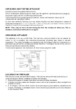
Page 6: ...e operates p 120 Volt grounded outlet ion manual switches remote and heater to m orrectly ices your new electric fireplace has been de and 35 95 During the cold win erature before turning it on e of odor during the first few minutes of ever occur again 120 Volts The cord has a plug as shown in for connecting three blade grounding typ unding lug extending from the adapter must properly grounded out...

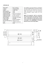
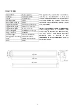
Page 7: ...32 7 8 16 or 83 5 cm 40 6 cm BTU 4095 This appliance has been tested in accordance with the UL Standard 2021 for fixed and location dedicated electric room appliances in the United States and Canada If you need assistance during installation please contact your local dealer NOTE This appliance must be electrically wired and grounded in accordance with local codes In the absence of local codes use ...

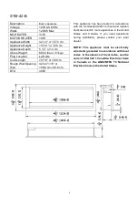
Page 8: ...42 3 4 16 or 108 6 cm 40 6 cm BTU 4095 This appliance has been tested in accordance with the UL Standard 2021 for fixed and location dedicated electric room appliances in the United States and Canada If you need assistance during installation please contact your local dealer NOTE This appliance must be electrically wired and grounded in accordance with local codes In the absence of local codes use...

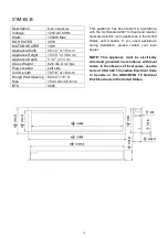
Page 9: ...50 3 4 16 or 128 9 cm 40 6 cm BTU 4095 This appliance has been tested in accordance with the UL Standard 2021 for fixed and location dedicated electric room appliances in the United States and Canada If you need assistance during installation please contact your local dealer NOTE This appliance must be electrically wired and grounded in accordance with local codes In the absence of local codes use...

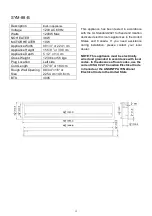
Page 10: ...0 3 4 16 or 154 3 cm 40 6 cm BTU 4095 This appliance has been tested in accordance with the UL Standard 2021 for fixed and location dedicated electric room appliances in the United States and Canada If you need assistance during installation please contact your local dealer NOTE This appliance must be electrically wired and grounded in accordance with local codes In the absence of local codes use ...

Page 11: ...4 3 4 16 or 189 9 cm 40 6 cm BTU 4095 This appliance has been tested in accordance with the UL Standard 2021 for fixed and location dedicated electric room appliances in the United States and Canada If you need assistance during installation please contact your local dealer NOTE This appliance must be electrically wired and grounded in accordance with local codes In the absence of local codes use ...

Page 12: ...88 3 4 16 or 225 4 cm 40 6 cm BTU 4095 This appliance has been tested in accordance with the UL Standard 2021 for fixed and location dedicated electric room appliances in the United States and Canada If you need assistance during installation please contact your local dealer NOTE This appliance must be electrically wired and grounded in accordance with local codes In the absence of local codes use...

Page 13: ... 100 3 4 16 or 255 9 cm 40 6 cm BTU 4095 This appliance has been tested in accordance with the UL Standard 2021 for fixed and location dedicated electric room appliances in the United States and Canada If you need assistance during installation please contact your local dealer NOTE This appliance must be electrically wired and grounded in accordance with local codes In the absence of local codes u...

Page 14: ...nit is an electrical appliance that is NOT watertight and must be installed as to prevent water from entering unit This must be installed away from shows tubs etc Never locate fireplace where it may fall into a bathtub or other water container All wiring connections to line power shall be in accordance with local building code requirements Inquires about local codes and regulations must be done pr...

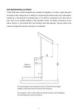
Page 15: ...aining the listed mantel and combustibles clearances a rain protection overhang factor of 1 2 shall be constructed to the front and to each side of the installed appliance See illustration below All wiring connections to line power shall be in accordance with local building code requirements Inquires about local codes and regulations must be done prior to installation ...

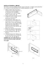
Page 16: ... bit and inser plugs into the holes 4 Remove the hanger from the by removing the screws See 5 Fasten the hanger to the wall Figure 3 6 To prevent fireplace from mov the provided safety screw to f fireplace to the wall See Figu WARNING Be sure that the bo been fixed firmly enough to wi the weight 16 L MOUNT fferent materials used to build walls it is highly er before you install this appliance on a...

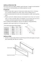
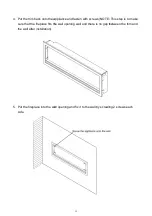
Page 17: ...erent materials used to build walls it is highly er before you install this appliance on a wall not prone to moisture and is located at least 0 91 ials such as curtains drapes furniture bedding on on the floor and store the appliance in a saf framed opening to accommodate the size of nd the edge of the appliance Any new wirin nd national codes and other applicable regulat ppliance to make sure the...

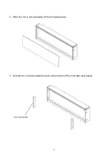
Page 18: ...2 When the trim is removed tak 3 Unscrew the 2 screws located 18 ed take off the front glass panel ocated on each side and take off the inner side r side steel panels ...

Page 19: ...all after installation 5 Put the fireplace into the wall side 19 he appliance and fasten with screws NOTE T ts the wall opening well and there is no gap be e wall opening and fix it to the wall by screwing TE This step is to make ap between the trim and ewing 2 screws each ...

Page 20: ...6 Remove the trim following ST 7 Put back the front glass pane decoration 20 ng STEP 1 Screw back the inner side steel pa panel and screw back the trim after you finish eel panels finish the media ...

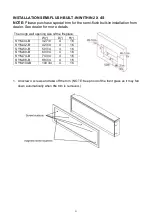
Page 21: ... SYM 74 B 74 3 4 SYM 88 B 88 3 4 SYM 100 B 100 3 4 1 Unscrew 4 screws and take o down automatically when the 21 FLUSH BUILT IN WITHIN 2 X 4 S special trim for the semi flush built in i more details ze of the fireplace D H 4 16 4 16 4 16 4 16 4 16 4 16 4 16 take off the trim NOTE Keep hold of the front n the trim is removed in installation from e front glass as it may fall ...

Page 22: ...2 When the trim is removed tak 3 Unscrew the 2 screws located 22 ed take off the front glass panel ocated on each side and take off the inner side r side steel panels ...

Page 23: ... with screws NOTE This step is to make sure that the fireplace fits the wall opening well and there is no gap between the trim and the wall after installation 5 Put the fireplace into the wall opening and fix it to the wall by screwing 2 screws each side ...

Page 24: ...24 6 Remove the trim following STEP 1 Screw back the inner side steel panels 7 Put back the front glass panel and screw back the trim after you finish the media decoration ...

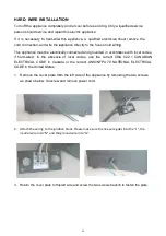
Page 25: ... cool before servicing Only a qu repair this electric appliance wire this appliance a qualified electrician mu he appliance directly to the house hold wiring ctrically connected and grounded in accordan ence of local codes use the current CSA anada or the current ANSI NFPA 70 NATIO e from the left side of the appliance by removin rew and remove power cord ction block Please make sure the live wire...

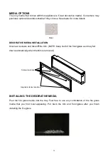
Page 26: ...stalling the fire glass 26 s with this appliance is Clear decorative med ve media if they choose See dealer for more d Clear TALLATION e off the trim NOTE Keep hold of the front gla he trim is removed CORATIVE MEDIA into the tray Feel free to use any combinati t appealing Put back the trim and front gla media Consumers may ore details nt glass as it may fall bination of the fire glass nt glass aft...

Page 27: ... off and the cycle will continue The LED indicator will be PURPLE in colour under this mode 2 Flame effect Press the button marked Flame to adjust the flame brightness The flame brightness will cycle through Low Medium High OFF NOTE If operated at the Low heat setting the fireplace will not provide as much heat output as in the High heat setting however the low setting will not require as much ele...

Page 28: ...ireplace BLUE Each click adjusts the intensity of the blue flame Use alone or in addition to yellow and or orange YELLOW Each click adjusts the intensity of the yellow flame Use alone or in addition to blue and or orange ORANGE Each click adjusts the intensity of the orange flame Use alone or in addition to yellow and or blue HEATER ON OFF Turns the heater ON OFF It will recall the last settings u...

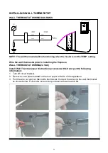
Page 29: ...shown below Follow the in 29 HERMOSTAT ING DIAGRAMS prior to installing the fireplace ING 24 VAC er instructions provided with kit and per the ated on the rear upper left side of the applianc t the inside thermostat Connect the wires to th the instructions provided with wall switch kit er the following pliance s to the wall thermostat h kit NOTE The wall thermostat will t will be functioning when ...

Page 30: ...5 601141B 601141B 601141 601141 LED STRIP FOR FLAME 6 601142B 7 601136B 601136B LED STRIP FOR EMBER BED 8 601137B 601137B 601137B 601137B 9 10101225 FLAME MOTOR 1 10 3200505 3201505 3155505 3156505 FLICKER ASSEMBLY 1 11 FIRE BOX 1 12 601032B CONTROL PANEL 1 13 601097B 601092C CIRCUIT BOARD 1 14 602130B BLOWER AND HEATER ASSEMBLY 1 15 10114001B TEMPERATURE SENSOR 1 16 3001506B REMOTE RECEIVER 1 17 ...

Page 31: ...ED STRIP FOR FLAME 6 601142 601142 601142 7 601136B 601136B 601136B LED STRIP FOR EMBER BED 8 601137B 601137B 601137B 9 10101225 FLAME MOTOR 1 10 3157505 3205505 3206505 FLICKER ASSEMBLY 1 11 FIRE BOX 1 12 601032B CONTROL PANEL 1 13 601092C CIRCUIT BOARD 1 14 602130B BLOWER AND HEATER ASSEMBLY 1 15 10114001B TEMPERATURE SENSOR 1 16 3001506B REMOTE RECEIVER 1 17 10105064 REMOTER 1 NOTE Remote contr...

Page 32: ...EXPLODED VIEW 32 ...
Page 33: ... fuse has blown Replace the fuse Appliance will not come on when switch is flipped to ON Appliance is not plugged into an electrical outlet Check plug and plug in Appliance has overheated and safety device has caused the thermal switch to disconnect Turn off the main switch allow appliance to cool for 10 minutes then turn on Circuit board is burnt out Inspect the circuit board and replace if neces...

Page 34: ...SERVICE HISTORY This heater must be serviced annually depending on usage Date Dealer Name Service Technician Name Service Performed Special Concerns NOTES 34 ...

Page 35: ... of purchase of the cover is required for any warranty claims Defects Defects must be brought to the attention of the selling dealer Please have your proof of purchase catalogue model and serial numbers available when contacting dealer any and all service under the limited warranty requires a proof of purchase of the product Should a product or part covered by this limited warranty be proven to be...

Reviews: