background image

16 

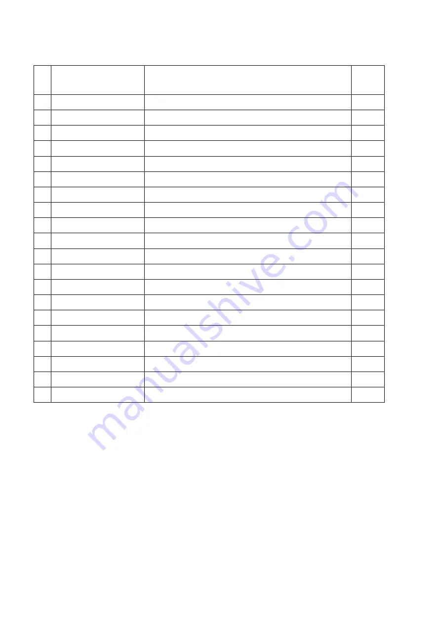
REPLACEMENT PARTS 

NO 

PART NUMBER 

DESCRIPTION 

QTY. 

TOP PANEL 

BACK TOP PANEL 

601097B

CIRCUIT BOARD 

602067D 

BLOWER AND HEATER ASSEMBLY 

3056001

FIREPLACE BOX 


TOP LED STRIP 

10104010 

TOP LED BRACKET 

601036 

CONTROL PANEL 

301506 

REMOTE RECEIVER 

10103007 

POWER CORD 

10104002 

SWITCH 

10 

11 

3056505 

FLICKER ASSEMBLY 

12 

601144

FLAME LED STRIP 

13 

601144

TRAY LED STRIP 

14 

3056506 

FLICKER ASSEMBLY TRAY 

15 


BACK GLASS

16 

10702150 

BOTTOM GLASS 

17 

10702150

TRAY GLASS

18 


FRONT FLAT GLASS 

10105063B

REMOTE 

10125025

10701200C

10701164

Summary of Contents for WM-BI-2428-VLR-BG

Page 1: ...FUTURE REFERENCE SAFETY INFORMATION WARNING For your safety always comply with all warnings and safety instructions contained in this manual to prevent personal injury or property damage Do not store...

Page 2: ...E 4 LOCATING THE FIREPLACE 4 CLEARANCES WHEN BUILT IN 5 INSTALLATION WALL MOUNT 7 WM BI 2428 VLR BG 8 INSTALLATION OVERVIEW MASONRY FIREPLACES 9 INSTALLATION OVERVIEW ZERO CLEARANCE METAL FIREPLACES 1...

Page 3: ...F before removing the plug from the outlet 9 Do not insert or allow foreign objects to enter any ventilation or exhaust opening as this may cause an electric shock fire or damage to the heater 10 To p...

Page 4: ...plug as shown in A An adapter as shown in C is available for connecting three blade grounding type plugs to two slot receptacles The green grounding lug extending from the adapter must be connected t...

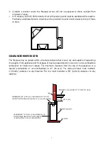
Page 5: ...e of supporting the weight of the appliance and front glass It may be placed directly on wood or a non combustible surface not on linoleum or carpet The minimum clearance from the top of the appliance...

Page 6: ...n of fireplace when it install in different way a Fireplace with flat glass insert to the wall b Fireplace with curve glass insert to the wall c Fireplace with curve glass in a corner d Fireplace with...

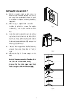
Page 7: ...hieve this 3 Check the wall to ensure there is no wiring pipe wires etc in the area to be drilled Drill 8 or more holes 8mm diameter 40mm depth using a suitable size drill and put the wall plugs into...

Page 8: ...een tested in accordance with the UL Standard 2021 for fixed and location dedicated electric room appliances in the United States and Canada If you need assistance during installation please contact y...

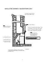
Page 9: ...eted grounded receptacle may be placed within the fireplace Do not place it above the fireplace insert The surround glass extends 1 below the base of the insert Attach the This fireplace has been alte...

Page 10: ...bolts to provide adequate leveling Silicone The surround glass extends 1 below the base of the insert A Code Conforming jacketed grounded receptacle may be placed within the fireplace Do not place it...

Page 11: ...electrically connected and grounded in accordance with local codes if hard wired In the absence of local codes use the current CSA C22 1 CANADIAN ELECTRICAL CODE in Canada or the current ANSI NFPA 70...

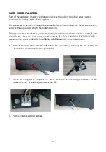
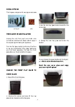
Page 12: ...dia that you find most appealing Put back the front glass after you finish install the fire glass CHANGE THE FRONT FLAT GLASS TO CURVE GLASS 1 Take off the front flat glass 2 Unscrew the screws and ta...

Page 13: ...be turned off and the cycle will continue The LED indicator will be PURPLE in colour under this mode 4 Flame effect Press the button marked to adjust the flame brightness The flame brightness will cy...

Page 14: ...s of setting memory DISPLAY RED button Adjust the red c olor brightness of flame and tray DISPLAY YELLOW button Adjust the yellow color brightness of flame and tray DISPLAY ORANGE button Adjust the or...

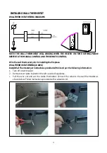
Page 15: ...mostat prior to installing the fireplace WALL THERMOSTAT WIRING 24 AWG Install Wall Thermostat per instructions provided with kit and per the following information 1 Turn off circuit breaker 2 Remove...

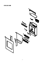
Page 16: ...IP 1 7 10104010 TOP LED BRACKET 1 6 601036 CONTROL PANEL 1 7 301506 REMOTE RECEIVER 1 8 10103007 POWER CORD 1 9 10104002 SWITCH 1 10 11 3056505 FLICKER ASSEMBLY 1 12 601144 FLAME LED STRIP 1 13 601144...

Page 17: ...17 EXPLODED VIEW...

Page 18: ...se has blown Replace the fuse Appliance is not plugged into an electrical outlet Check plug and plug in Appliance has overheated and safety device has caused the thermal switch to disconnect Turn off...

Page 19: ...19 SERVICE HISTORY This heater must be serviced annually depending on usage Date Dealer Name Service technician Name Service Performed Special Concerns NOTES...

Page 20: ...20...
Reviews: