background image

The AMAV Micro20 speakers & Macro80P powered sub woofer 
continue to form  a compact, yet extremely high quality sub/sat 
speaker system. The Micro20 speakers are a sleek design 
in die cast aluminium featuring a 3” woofer & 1/2” tweeter 
supplied as 
a pair, with brackets. The Micro20 speakers are rated at 
30 watts RMS & their small size belies their impressive audio 
performance. 

The Macro80P sub woofer is the perfect partner for the 
Micro20P speakers. Featuring dual 6.5” woofers, an onboard 
80 watt D class amplifi er for sub frequencies as well as 4 x 20 
watt amplifi ers to power Micro20’s, the Macro80P represents 
excellent audio reproduction as well as great value for money.

A remote volume, treble & bass control wall plate is also 
available for the Macro80P to allow for system control in a 
permanent installation.

Congratulations on your purchase of the Micro20/Macro80p 
system.

I N T R O D U C T I O N   3

R E A R   PA N E L  

4

M O U N T I N G   D E TA I L  

5

S P E C I F I C AT I O N S   6

I N T R O D U C T I O N   A N D   C O N T E N T S

PA G E   3

M I C R O 2 0 / M A C R O 8 0 P   I N S TA L L AT I O N   &   O P E R AT I O N   M A N U A L

AUS, EUR, USA

REV A: Oct 2007

This symbol is intended to alert the user to the presence 
of uninsulated “dangerous voltage” within the products 
enclosure that may be of suffi 

cient magnitude to 

constitute a risk of electric shock to persons.

This symbol is intended to alert the user to the presence 
of important operational and maintenance (servicing) 
instructions in the literature accompanying the 
appliance.

To prevent electric shock do not use this (polarised) plug 
with an extension cord, receptacle or other outlet unless 
the blades can be fully inserted to prevent blade exposure. 
To prevent electric shock, match wide blade of plug to 
wide slot, fully insert.

Caution:

CAUTION

CAUTION: TO REDUCE THE RISK OF ELECTRIC SHOCK,

DO NOT REMOVE COVER (OR BACK),

NO USER SERVICEABLE PARTS INSIDE,

REFER SERVICING TO QUALIFIED SERVICE PERSONAL.

WARNING!

TO REDUCE THE RISK OF FIRE OR ELECTRIC SHOCK

DO NOT EXPOSE THIS EQUIPMENT TO RAIN OR MOISTURE.

RISK OF ELECTRIC SHOCK

DO NOT OPEN

Summary of Contents for MACRO80P

Page 1: ...ustralian Monitor 1 Clyde Street Silverwater NSW 2128 Australia 61 2 9647 1411 www australianmonitor com au SERVICE INFORMATION MACRO80P POWERED LOUDSPEAKER CONTENTS OPERATION MANUAL SCHEMATIC DIAGRAM...

Page 2: ...MICRO20 MACRO80P ACTIVE TWO WAY STEREO SPEAKER SYSTEM INSTALLATION AND OPERATION MANUAL...

Page 3: ...producing devices 13 Do not block fan intake or exhaust ports Do not operate equipment on a surface or in an environment which may impede the normal flow of air around the unit such as a bed rug weath...

Page 4: ...3 REAR PANEL 4 MOUNTING DETAIL 5 SPECIFICATIONS 6 INTRODUCTION AND CONTENTS PAGE 3 MICRO20 MACRO80P INSTALLATION OPERATION MANUAL AUS EUR USA REV A Oct 2007 This symbol is intended to alert the user t...

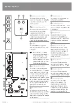
Page 5: ...llowing signal on either the left or right inputs to feed all speakers SPEAKER OUTPUTS These outputs are used to connect the MICRO20 satellite speakers This signal is electronically high pass fil tere...

Page 6: ...MOUNTING DETAIL PAGE 5 MICRO20 MACRO80P INSTALLATION OPERATION MANUAL MICRO20 BRACKET MOUNTING DETAIL WMVC MOUNTING DETAIL...

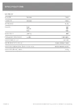
Page 7: ...r 75mm TWEETER Diameter 25mm IMPEDANCE 8 ohm POWER RMS 30W Program 60W Peak 120W SENSITIVITY 1W 1m 84dB FREQUENCY RESPONSE 3dB 140Hz 30kHz DISPERSION H X V 120 x 90 DIMENSIONS H X W X D 150mm x 90mm x...

Page 8: ...hms 1 THD RMS 25W 2 ohms 1 THD RMS Not Recommended SUB BANDPASS 40Hz 175Hz SATELLITE BANDPASS 80Hz 30kHz INPUT SENSITIVITY 85mV CURRENT DRAW 1 2A max FUSE RATING 250V 2A SB DIMENSIONS H X W X D 405mm...

Page 9: ...31 Walsh Street Thebarton SA 5031 PO Box 157 Hindmarsh SA 5007 Phone 08 8352 4444 Fax 08 8352 4488 Email sa audiotelex com au PERTH WA SALES 3 11 Howe Street Osborne Park WA 6017 PO Box 1281 Osborne P...

Page 10: ...C 100E R47C 220E R45C 2K2 R46C 100K R50A 2K2 R53A 1M R52A 47K R51A 47K R55A 100E R54A 1M R57A 100K R56A 10K R58A 10k R48A 2K2 R49A 100E R47A 220E R45A 2K2 R46A 100K R52B 47K R50D 2K2 R53D 1M R52D 47K...

Page 11: ...0E 1 4W R8D 10E 1W R5D 4 7Ohm R3D 68K R2D 22K R1B 22K R13 R17 10K R16 4K7 R14 10K R12 10K R11 22K R15 10K R4C 10E 1 4W R8C 10E 1W R5C 4 7Ohm 1W R3C 68K R2C 22K R1C 22K R4A 10E 1 4W R8A 4 7Ohm 1W R3A 6...

Page 12: ...F C45 1KP Q1 C3198Yx2 C40 100uF 25Vx2 C41 Q2 Q3 A1266Y D3 1N4148 Q4 C3198Y C48 0 1uF C49 47uF 25V C50 0 1uF C46 47uF C4A 1uF C47 47uF 25V R38 3K3 R39 10K R40 10K R42 22K R41 10K R46 10K R51 100K R45 1...

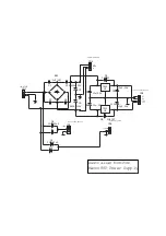
Page 13: ...C8 10u 25V C7 10u 25V 1 2 3 U1 7812 2 3 1 U2 7912 D5 1N4007 C6 C5 6800u 50V C4 C3 C2 C1 1uF X4 BR1 CN3 CN2 CN1 TO PN3 OF POW AMP PCB TO SUB WOOFER PCB CN6 V V GND TO POW AMP PCB 12V G A 12V G B FROM...

Reviews: