background image


Settings 


Primera  BAG0175.3  07.18


109 


8.2 

Setting the spread rate - Performing the calibration test 


  1.  Enter the desired spread rate on the control terminal. 

  2.  Perform a calibration test to determine the calibration factor. 

The spread rate must be set for 


Seed 


Fertiliser (optional) 


Perform a calibration test after setting the desired spread rate! 

  1.  Perform a calibration test for seed. 

  2.  Perform a calibration test for fertiliser. 


When spreading seed and fertiliser at the same time, the spread rate 
is limited.  

15 km/h: 

Maximum seeding rate: 250 kg/ha  

Minimum seeding rate:. 2 kg/ha (1 dosing unit) 

Maximum fertiliser rate: 80 kg/ha 

8.2.1 

Calibration test 


The calibration test checks whether the preset spread rate matches 
the actual spread rate. 

Always carry out a calibration test: 


when changing the seed type/fertiliser 


if the seed type is identical, but size grain, grain shape, specific 
weight and dressing are different 


after exchanging the dosing rollers 


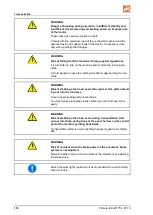
WARNING 

Never step between the machine and the exact harrow before the 
stop tap is closed which blocks the hydraulics of the exact har-
row. 


When spreading the seed and fertiliser at the same time, carry out 
one calibration test each for the seed and fertiliser separately. 


Gears not used for the calibration test should be set to po-
sition 0.


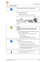
Whenever possible calibrate and set the seed rate after the journey to 
the field with the filled seed hopper. 

This ensures a more accurate seed rate. 


Summary of Contents for DMC 6000-2

Page 1: ...rating Manual az DMC 6000 2 DMC 6000 2C Trailed seed drill MG6489 BAG0175 3 07 18 Printed in Germany Please read this operating manual before first commis sioning Keep it in a safe place for future use en ...

Page 2: ...itself The person in question would not only harm himself but also make the mistake of blaming the machine for pos sible failures instead of himself In order to ensure success one should enter the mind of a thing make himself familiar with every part of the ma chine and get acquainted with how it s handled Only in this way could you be satisfied both with the machine and with yourself This goal is...

Page 3: ...ZONEN WERKE H DREYER GmbH Co KG Postfach 51 D 49202 Tel Fax E mail Hasbergen 49 0 5405 501 0 49 0 5405 501 234 amazone amazone de Spare part orders Online spare parts catalogue www amazone de When ordering spare parts always specify the ten digit machine identification number Formalities of the operating manual Document number MG6489 Compilation date 07 18 Copyright AMAZONEN WERKE H DREYER GmbH Co...

Page 4: ...he safety information Only after careful reading will you be able to benefit from the full scope of your newly purchased machine Please ensure that all the machine operators have read this operating manual before commissioning the machine Should you have any questions or problems please consult this op erating manual or contact your local service partner Regular maintenance and timely replacement ...

Page 5: ...y conscious working 22 2 16 Safety information for users 23 2 16 1 General safety and accident prevention information 23 2 16 2 Hydraulic system 26 2 16 3 Electrical system 27 2 16 4 Universal joint shaft operation 28 2 16 5 Attached machines 29 2 16 6 Brake system 30 2 16 7 Tyres 31 2 16 8 Operation of the seed drill 31 2 16 9 Cleaning maintenance and repairs 31 3 Loading and unloading 32 4 Produ...

Page 6: ...5 20 Twin Terminal optional 75 5 21 Distributor head and tramline circuit 76 5 21 1 Tramline rhythm 77 5 22 Jack 81 5 23 Jack for the drawbar eye ball coupling 82 5 24 Hopper with swivelable cover 83 5 25 Working platform 84 5 26 Camera system 85 5 27 Work lights 85 5 28 Level sensor 86 5 29 Filling auger optional 87 5 30 Tramline marker optional 88 6 Commissioning 89 6 1 Checking the suitability ...

Page 7: ... and dosing unit 126 11 Faults 128 12 Cleaning maintenance and repairs 129 12 1 Cleaning 131 12 1 1 Cleaning the distributor head workshop 132 12 2 Lubrication specifications workshop work 133 12 2 1 Lubrication point overview 133 12 2 2 Lubricating axles 135 12 3 Service plan overview 136 12 4 Axle and brake 138 12 4 1 Inspection instructions for the dual circuit service brake system 143 12 5 Par...

Page 8: ...ns specified in the operating manual are always seen from the direction of travel 1 3 Diagrams used Handling instructions and reactions Activities to be carried out by the user are given as numbered instruc tions Always keep to the order of the handling instructions The reac tion to the handling instructions is given by an arrow Example 1 Handling instruction 1 Machine response to instruction 1 2 ...

Page 9: ... To replace damaged warning pictograms If you still have queries please contact the manufacturer Obligations of the user Before starting work anyone charged with working with on the ma chine is obliged To comply with the basic workplace safety instructions and acci dent prevention regulations To read and understand the section General safety information of this operating manual To read the section...

Page 10: ...ble These shall be available to the operator at the latest on the comple tion of the contract Guarantee and liability claims for damage to peo ple or goods will be excluded if they can be traced back to one or more of the following causes Improper use of the machine Improper installation commissioning operation and mainte nance of the machine Operation of the machine with defective safety equipmen...

Page 11: ...e diate death or serious physical injury WARNING Indicates a medium risk which could result in death or serious physical injury if not avoided If the instructions are not followed then this may result in death or serious physical injury CAUTION Indicates a low risk which could incur minor or medium level physical injury or damage to property if not avoided IMPORTANT Indicates an obligation to spec...

Page 12: ...ssible for the user and mainte nance personnel Check all the available safety equipment regularly 2 4 Safety and protection equipment Before each commissioning of the machine all the safety and protec tion equipment must be properly attached and fully functional Check all the safety and protection equipment regularly Faulty safety equipment Faulty or disassembled safety and protection equipment ca...

Page 13: ...n shall be considered as having been instructed if they have been instructed in the tasks they have to carry out and in the possible risks in the case of improper behaviour and also have been informed about the necessary protective equipment and measures 3 People with specialist technical training shall be considered as a specialist Due to their specialist training and their knowledge of the appro...

Page 14: ...out replacement work Check all the screw connections for a firm seat On completing maintenance work check the function of safety and protection equip ment 2 10 Constructive changes You may make no changes expansions or modifications to the ma chine without the authorisation of AMAZONEN WERKE This is also valid when welding support parts Any expansion or modification work shall require the written ...

Page 15: ...ar and spare parts from third parties does not guaran tee that they have been constructed in a way as to meet the require ments placed on them AMAZONEN WERKE accepts no liability for damage arising from the use of non released spare parts wear parts or auxiliary materials 2 11 Cleaning and disposal Handle and dispose of any materials used carefully in particular When carrying out work on lubricati...

Page 16: ...gram consists of two fields Field 1 is a pictogram describing the danger surrounded by triangular safety symbol Field 2 is a pictogram showing how to avoid the danger Warning pictograms explanation The column Order number and explanation provides an explanation of the neighbouring warning pictogram The description of the warning pictograms is always the same and specifies in the following order 1 ...

Page 17: ... Instructions Primera BAG0175 3 07 18 17 2 13 1 Positioning of warning pictograms and other labels Warning pictograms The following diagrams show the arrangement of the warning picto grams on the machine Fig 1 Fig 2 ...

Page 18: ...treads or platforms Ensure that no one rides with the machine MD 084 Risk of the entire body being crushed as a result due to standing in the swivel range when machine parts are being lowered This risk can cause extremely serious and poten tially fatal injuries It is prohibited to stand in the swivel range of the machine when machine parts are be ing lowered Instruct personnel to leave the swivel ...

Page 19: ...d and understand the operating manual safe ty information before starting up the machine MD 096 Hazard from escaping high pressure hydrau lic fluid due to leaking hydraulic hose lines This hazard may cause serious injuries perhaps even resulting in death if escaping high pressure hydraulic fluid passes through the skin and into the body Never attempt to stop leaks in hydraulic hose lines with your...

Page 20: ...ractor and the machine against unintentional start up and rolling before any intervention in the machine Depending on the type of intervention read and understand the information in the rele vant sections of the operating manual MD 114 This symbol indicates a lubrication point MD139 The torque of the screw connection is 450 Nm MD 174 Danger from unintended continued move ment of the machine Causes...

Page 21: ...d attached machine This danger can cause extremely serious and potentially fatal injuries Do not remain in the danger area between tractor and machine while the tractor engine is running and the tractor is not secured against unintentionally rolling away Instruct anyone in the danger area between tractor and machine to leave the danger ar ea while the tractor engine is running and the tractor is n...

Page 22: ...on secured working areas Failure of important machine functions Failure of prescribed methods of maintenance and repair Danger to people through mechanical and chemical impacts Risk to environment through leakage of hydraulic fluid 2 15 Safety conscious working Besides the safety information in this operating manual the national general workplace safety and accident prevention regulations are bind...

Page 23: ...the driving characteristics of the tractor and the connected machine Connecting and disconnecting the machine Only connect and transport the machine with tractors suitable for the task When connecting machines to the tractor s three point hydraulic system the attachment categories of the tractor and the ma chine must always be the same Connect the machine to the prescribed equipment in accordance ...

Page 24: ... you understand all the equip ment and actuation elements of the machine and their function There is no time for this when the machine is already in opera tion Do not wear loose fitting clothing Loose clothing increases the risk over being caught by drive shafts Only start up the machine when all the safety equipment has been attached and is in the safety position Comply with the maximum load of t...

Page 25: ...brake delay for the loaded vehicle combination tractor plus connected machine Check the brake power before moving off When turning corners with the machine connected take the broad load and balance weight of the machine into account Before moving off ensure sufficient side locking of the tractor lower links when the machine is fixed to the three point hydrau lic system or lower links of the tracto...

Page 26: ...ο Remove the ignition key Have the hydraulic hose line checked at least once a year by a specialist for proper functioning Replace the hydraulic hose line if it is damaged or worn Only use AMAZONE original hydraulic hose lines The hydraulic hose lines should not be used for longer than six years including any storage time of maximum two years Even with proper storage and approved use hoses and hos...

Page 27: ...ntact with earth may cause an explosion Risk of explosion avoid the production of sparks or the presence of naked flames in the vicinity of the battery The machine can be equipped with electronic components the function of which may be influenced by electromagnetic interfer ence from other units Such interference can pose risks to peo ple if the following safety information is not followed ο In th...

Page 28: ... the operating manual from the PTO shaft manufacturer When turning corners observe the permitted bending and dis placement of the PTO shaft Before switching on the universal joint shaft check that the se lected universal joint shaft speed of the tractor matches the per mitted drive rev speed of the machine Instruct people to leave the danger area of the machine before you switch on the universal j...

Page 29: ...ent equipment on the tractor and the machine drawbar Only couple approved combinations of vehicles tractor and at tached machine In the case of single axle machines observe the maximum per mitted drawbar load of the tractor on the attachment equipment Ensure that the tractor has sufficient steering and braking power Machines connected to a tractor can influence your driving be haviour as well as t...

Page 30: ... on the sealing rings on the hose couplings of the supply and brake lines Only move off with the machine connected when the pressure gauge on the tractor shows 5 0 bar Drain the air tank every day Before driving without the machine lock the hose couplings on the tractor Hang the hose couplings of the machine supply and brake lines in the appropriate empty couplings When filling up or replacing the...

Page 31: ... Before transportation remove the thrust collars of the tramline marker Do not place any parts in the seed hopper Before transportation lock the track marker construction dependent in the transport position 2 16 9 Cleaning maintenance and repairs Only carry out cleaning maintenance and repair work on the machine when ο The drive is switched off ο The tractor engine is at a standstill ο The ignitio...

Page 32: ...oading and unloading as long as the tractor fulfils the power re quirements Compressed air brake system Only move off with the machine connected when the pressure gauge on the tractor shows 5 0 bar If the machine is to be loaded onto or unloaded from a transport vehi cle it must be coupled to a suitable tractor Loading A person to provide manoeuvring instructions is required for loading Secure the...

Page 33: ...ine in working position 1 Chisel 2 Supporting rolls 3 Coulter frame 4 Seed hoses 5 Seed distributor 6 Fertiliser distributor optional 7 Seed hopper and fertiliser hopper optional 8 Foldable boom 9 Jack 10 Drawbar with coupling device 11 Hose cabinet 12 Hydraulic fluid tank with filter and pressure relief valve ...

Page 34: ...earbox 5 Dosing unit for fertiliser with injector and Vario gearbox optional 6 Parking brake 7 Depth adjustment of the coulter gangs 8 Markers 9 Wheel chocks 10 Working lights 11 Maintenance platform with ladder 4 2 Safety and protection equipment 1 Rails on maintenance platform 2 Road safety bar on the exact following har row for road transport 3 Road safety bars on exact harrow for road transpor...

Page 35: ...ection to on board computer Connection to hydraulic brake Pneumatic brake system ο Brake line with coupling head yellow ο Supply line with coupling head red Fig 6 4 4 Transportation equipment 1 2 rear lights 2 brake lights 2 turn indicators 2 2 warning signs square 3 Reflectors yellow at side with max 3 m spacing 4 registration plate holder with lighting 5 2 red reflectors triangular Fig 7 1 2 war...

Page 36: ... can be travelled Along the contours Direction of travel to left 20 Direction of travel to right 20 Along the gradient Up the slope 20 Down the slope 20 Intended use also comprises Compliance with all the instructions in this operating manual Execution of inspection and maintenance work Exclusive use of genuine AMAZONE spare parts Other uses to those specified above are forbidden and shall be con ...

Page 37: ...ations of the appropriate section shall be valid No one may stand in the machine danger area as long as the tractor engine is running with a connected PTO shaft hydraulic system as long as the tractor and machine are not protected against unintentional start up and running The operating person may only move the machine or switch or drive the tools from the transport position to the working positio...

Page 38: ... 7 Rating plate and CE marking The rating plate specifies Vehicle ID no Implement ID no Product Basic weight in kg Perm drawbar load kg Perm rear axle load kg Perm system pressure bar Perm total weight kg Factory Model year Year of manufacture Fig 9 ...

Page 39: ...ing point category Kat 3 4 5 Hopper volume 4200 l seed 3150 l fertiliser 1050 l Hopper volume with hopper ex tension 800 l 5000 l seed 3750 l fertiliser 1250 l Hopper volume with hopper ex tension 1600 l 5800 l seed 4350 l fertiliser 1450 l Hopper width 2 9 m Row spacing 18 75 cm 25 cm Number of sowing coulters 32 24 Tare weight basic weight 8100 kg 7200 kg Tyres Air pressure LD178 BKT FLOTATION 6...

Page 40: ...oad permissible tyre load capacity per tyre pair The permissible total weight is the sum of the smaller value deter mined from Table 1 and 2 1 Permissible total weight 3000 kg 10000 kg 13000 kg depending on the axle drawbar load axle load 2 Permissible total weight 3000 kg _________ kg _________ kg depending on the wheel and forward speed drawbar load 2 x tyre load capacity Tyre load capacity per ...

Page 41: ... circuits of all standard makes of tractor Tractor control units At least 1 double acting and 1 single acting tractor control unit Maximum 3 double acting tractor control units and one free re turn flow Universal joint shaft Required speed 1000 rpm Direction of rotation Clockwise viewed from the rear towards the tractor Operational brake system Dual circuit service brake sys tem 1 hose coupling re...

Page 42: ... fertilisation can be carried out optional The seed is carried in the seed hopper For simultaneous fertilisation the hopper is split From the dosing unit which is driven by the drive wheel the set seed volume fertiliser volume enters the air flow created by the blower fan The air flow delivers the seed fertiliser to the distributor head which distributes the seed fertiliser evenly onto the chisel ...

Page 43: ...trate the respective hydraulic function The tractor control unit must be used in different types of activa tion depending on the hydraulic function Latched for a permanent oil circulation Tentative activate until the action is executed Float position free oil flow in the control unit Folding using tractor control units Function Hose identification yellow Pre selection via switch tap Folding fold o...

Page 44: ...y Maximum permissible pressure in oil return 10 bar Therefore do not connect the oil return to the tractor control unit but to a pressure free oil return flow with a large plug coupling WARNING For the oil return use only DN16 lines and select short return paths Pressurise the hydraulic system only when the free return has been correctly coupled Install the coupling union supplied on the pressure ...

Page 45: ...1 Place the tractor control unit in float position neutral 2 Release the hydraulic plugs from the hydraulic sockets 3 Fasten the hydraulic plugs in the empty coupling points 5 3 On board hydraulic system optional The on board hydraulic system is driven by the hydraulic slide on pump and is responsible for driving the fan Hydraulic slide on pump Connect the hydraulic slide on pump 1 1 Clean and gre...

Page 46: ...at low tractor engine speed Oil tank 1 Suction hose to the pump 2 Oil filter with contamination level indicator Fill the suction line of the pump with oil be fore initial operation Fig 12 3 Oil tank 4 Drain plug Fig 13 Oil cooler There is an oil cooler on the fan to cool the im plement s own oil supply to the fan Fig 14 ...

Page 47: ...uation button Push in up to the stop and release the service brake system e g to manoeu vre the uncoupled implement Pull out up to the stop and the imple ment is braked again by the supply pressure coming from the air reservoir 4 Hand lever for manual adjustment of the braking force Filled implement Empty implement Fig 15 1 Compressed air tank 2 Test connection for pressure gauge 3 Drain valve Fig...

Page 48: ...3 07 18 Line filter in the coupling head with sealing sur faces O ring and filter Fig 18 Brake axles 1 Membrane brake cylinder 2 Brake linkage 3 Linkage adjuster for brake camshaft 4 Brake camshaft 5 Connecting linkage for parking brake Fig 19 ...

Page 49: ...ed by the hose coupling of the supply line red The operating brake of the machine moves out of the brake position immediately the red hose coupling has been coupled 1 Open the tractor coupling head caps 2 Remove brake line coupling head yellow from the dummy cou pling 3 Check coupling head seals for damage and cleanness 4 Clean dirty seals replace damaged seals 5 Fasten the brake line coupling hea...

Page 50: ...ways keep to this order as otherwise the operating brake system will trip and may set the unbraked machine moving When the machine is uncoupled or separated from the trailer air is vented from the trailer brake valve supply line The trailer brake valve is automatically switched and operates the service brake system in dependently of the automatic load dependent braking force regulator 1 Secure the...

Page 51: ...Fig 20 Releasing the parking brake Ensure that the bowden cable is not lying on or rubbing against other vehicle parts When the parking brake is off the bowden cable must hang slightly slack Rotate the crank anticlockwise until the bowden cable becomes slack The parking brake is off Applying the parking brake Correct the adjustment of the parking brake if the spindle s tensioning travel is no long...

Page 52: ... 1 Loosen the hydraulic screw union if present 2 Protect the hydraulic plug and hydraulic socket against soiling using the dust protection caps 3 Store the hydraulic hose line in the hose cabinet 5 5 3 Emergency brake In event of the machine being released from the tractor during travel the emergency brake will brake the machine 1 Pulling cable 2 Brake valve with pressure accumulator 3 Hand pump t...

Page 53: ...ke When the implement is uncoupled the pressure accumulator presses hydraulic oil into the brake and decelerates the implement or into the hose line to the tractor and impedes the coupling of the brake line to the tractor In these cases relieve pressure using the hand pump on the brake valve 5 6 Safety chain for implements without brake system option Implements without a brake system or with a sin...

Page 54: ...nd is adjusted using the calibration test Fig 23 5 8 Dosing unit The dosing units dose the volume set at the Vario gearbox into the injector The machine has 1 Two seed dosing units 2 A fertiliser dosing unit optional Each dosing unit is fitted with a shutter slide in order to empty the dosing unit and replace the dosing rollers when the hopper is full The metering roller ground wheel is being driv...

Page 55: ...metering unit is equipped with an exchangeable metering roller The metering roller selection is dependent on the seed type the spread rate Dosing roller diagram table Single metering rollers cm 3 7 5 20 40 cm 3 120 210 350 cm 3 600 660 880 Double metering rollers cm3 40 240 420 1200 ...

Page 56: ...and the spread rate according to the following tables If the seed is not listed select the dosing roller of a seed that has a similar grain size Metering wheel without chambers The volume of some of the metering rollers can be changed by reposition ing removing the existing wheels and inserting metering wheels without chambers Fig 25 Parking position of the metering rollers Fig 26 ...

Page 57: ...ding Right Use half the working width on the left for seeding 2 Fertiliser sluice The fertiliser sluice does not have one sided switching 3 Injector The seed falls into the injector sluice and is di rected by the air current to the distributor head and then on to the coulters The injector has a flap for the calibration test or residual emptying Fig 27 5 10 Calibration trough The calibration quanti...

Page 58: ... coulter seed fertiliser Hopper for seed and fertiliser 1 Use the larger part of the hopper for the seed 2 Use the smaller part of the hopper for the spreading of fertiliser Metering unit 3 Equip the metering unit with a metering roller for fertiliser 4 Equip the metering unit for fertiliser with a metering roller for fertiliser Metering roller selection see pages 55 and 106 Scharabstand 18 75 cm ...

Page 59: ...ion Primera BAG0175 3 07 18 59 Seed path fertiliser path The seed hoses are numbered Standard seed hoses which are switched off when creating tramlines Alternative adjustable seed hoses for tramlines Row spacing 18 75 cm ...

Page 60: ...Structure and function 60 Primera BAG0175 3 07 18 Row spacing 25 cm ...

Page 61: ...iser Row spacing The simultaneous sowing of maize and spreading of fertiliser can take place in the following row spacings 75 cm 37 5 cm 18 75 cm Hopper for maize and fertiliser 1 Use the larger part of the hopper for the spreading of fertiliser 2 Use the smaller part of the hopper for the maize seed 3 Metering unit 4 Distributor Metering unit Equip the metering unit with the corresponding meterin...

Page 62: ...d row spacing several outlets on all of the distributors must be closed Various locking plates and sealing plugs are available depend ing on the size of the seed distributor for this purpose Fig 32 Fig 33 1 Outlets open 2 Outlets closed 3 Locking plate suspended 4 Sealing plug suspended ...

Page 63: ...g rhythm to 15 Replace the hoses Several hoses on the distributor must be replaced to obtain the de sired row spacing Replace the marked hoses Coulters Not all of the coulters are used when seeding maize Lift the coulters that are not being used and lock with a locating pin and an R clip This reduces the pulling force required by the tractor The locating pins are in the parking position Lift the m...

Page 64: ...0175 3 07 18 5 12 1 Overview of closed outlets in the distributor and switched off coulters Maize row spacing 18 75 cm Fertiliser row spacing 18 75 cm Here there are no closed outlets in the distributor and no switched off coulters Fig 35 ...

Page 65: ... BAG0175 3 07 18 65 Maize row spacing 75 cm c row spacing 75 cm Maize Install the locking plates according to Fig 41 Fertiliser Install the locking plates according to Fig 41 Replace the hoses 3 9 28 32 Switch off the coulter Fig 36 ...

Page 66: ...AG0175 3 07 18 Maize row spacing 75 cm Fertiliser row spacing 37 5 cm Maize Install the locking plates according to Fig 37 Fertiliser Install the sealing plugs according to Fig 37 Replace the hoses 3 9 28 32 Switch off the coulter Fig 37 ...

Page 67: ...rimera BAG0175 3 07 18 67 Maize row spacing 37 5 cm Fertiliser row spacing 37 5 cm Maize Install the sealing plugs according to Fig 38 Fertiliser Install the sealing plugs according to Fig 38 Replace the hoses 3 9 28 32 Fig 38 ...

Page 68: ...Structure and function 68 Primera BAG0175 3 07 18 Maize row spacing 75 cm Fertiliser row spacing 18 75 cm Maize Install the locking plates according to Fig 39 Replace the hoses 3 9 28 32 Fig 39 ...

Page 69: ...75 3 07 18 69 Maize row spacing 75 cm Fertiliser row spacing 18 75 cm Maize Install the locking plates according to Fig 40 Fertiliser Install the sealing plugs according to Fig 40 Replace the hoses 3 9 28 32 Switch off the coulter Fig 40 ...

Page 70: ... return line of the hydraulic line The hydraulic motor drives the blower and gen erates an air current The air current conveys the seeds from the injector sluice to the coulters Fig 41 Adjusting the fan speed Fan drive Actuate the red tractor control unit On board hy draulic system Adjust the PTO shaft speed if necessary the fan speed can be reduced using the pres sure relief valve ...

Page 71: ... 75 cm or 25 cm The double rollers installed behind the chisel coulter regulate the depth of the chisel coulters Fig 55 2 The double rollers are also responsible for closing the seeding furrow The placement depth is adjusted using the crank Fig 55 3 Fig 43 1 Standard bit for direct seeding the seed is laid in a row 2 Band bit for mulch seeding the seed is laid in a broader band ...

Page 72: ...chisel coulter can deflect and is protected from dam age After passing the obstacle or at the latest when lifting the seed ing coulters the chisel coulter is automatically moved back to its working position The spring preload 5 for the stone release must not be adjust ed WARNING Excessive wear of the coulter suspension when the stone release is under constant strain can lead to failure of the impl...

Page 73: ...for securing the raised transport position 3 Stop tap for securing the folded transport position The road safety bars are fastened onto the exact following harrow with elastic straps Fig 46 5 16 1 Roller harrow optional The roller harrow is mounted behind the exact following harrow and is lifted and folded together with the exact following harrow The roller harrow is usually used where the ground ...

Page 74: ... This mark serves as an orienta tion aid for the next run after turning After turn ing the tractor driver drives over the centre of the mark It is possible to set The length of the track marker The working intensity of the track marker depending on the type of soil Fig 49 Lift both track markers before turning at the end of the field before obstacles on the field before transportation WARNING It i...

Page 75: ...OBUS socket of the tractor and operated with the on board terminal An ISOBUS compatible control terminal makes it easy to control operate and monitor the imple ment Fig 50 5 20 Twin Terminal optional The communication with the ISOBUS compatible control terminal in the tractor cab takes place through the TwinTerminal optional The Twin Terminal is located in the metering area and saves the tractor d...

Page 76: ...hen creating the tramlines the tramline control system on the distribu tor head uses sliders Fig 65 1 to block the seed feeding lines to the seed lines Fig 65 2 of the tramline coulters The tramline coulters do not deposit any seeds on the ground The seed supply to the tramline coulters is inter rupted as soon as the electric motor Fig 65 3 closes the appropriate seed tubes Fig 65 2 in the distrib...

Page 77: ...ired tramline rhythm see table Fig 67 is derived from the required tramline spacing and the working width of the seed drill The table does not contain all the settable tramline rhythms A list of all the settable tramline rhythms can be found in the on board com puter operating manual The track width Fig 66 a of the tramline corresponds to that of the care tractor and is adjustable The track of the...

Page 78: ...of the on board computer operating manual Example Working width seed drill 6m Working width fertiliser spreader field sprayer 18m 18m tramline spacing 1 Look for the following in the adjacent table Fig 68 in column A the seed drills working width 6 m and in column B the tramline spacing 18 m 2 On the same line in column C take the reading for the tramline rhythm tramline rhythm 3 and set this in t...

Page 79: ...Structure and function Primera BAG0175 3 07 18 79 Fig 56 ...

Page 80: ...k with partial width switched off the drive of the appropri ate dosing roller is interrupted For an exact description see the on board computer operating manual Another option for creating tramlines with the tramline rhythm 4 6 and 8 is to begin with the full working width and the crea tion of a tramline see Fig 69 In this case the care machine works at half working width during the first field ru...

Page 81: ...may only be interrupted on the right side and tramline rhythm 6plus the seed feed to the tramline coulters may only be interrupted on the left side the seed feed to the tramline coulters is interrupted Work always starts on the right hand edge of the field Fig 58 5 22 Jack Jack raised during operation or transport Jack lowered when implement is uncou pled Raising lowering the jack 1 Pull out the p...

Page 82: ...ore uncoupling Lower the jack Att 64 1 using the hand crank Att 64 2 up to the stop until the trailer coupling is relieved Fig 60 The jack crank has a slow and a fast gear Att 65 Unloaded use the fast gear Loaded use the slow gear Pull out the hand crank Fast gear for the jack Push in the hand crank Slow gear for the jack high loads Fig 61 Fig 62 After actuating the crank swivel up the hand lever ...

Page 83: ... capacity of 800 l 1600 l Fig 63 Sieve for protection against foreign bodies Folding sieve in the seed hopper with sieve lock The sieve can be unlocked and folded using the unlocking tool 1 Handle with sieve locking mechanism 2 Unlocking tool Fig 64 Open the guard screen 1 Insert the unlocking tool into the handle 2 Hold the handle and turn the unlocking tool to the handle Guard screen locking mec...

Page 84: ...risk of falling Riding on the machine as a passenger is prohibited Always secure the ladder in the transport position 1 Folded up ladder one or two secured in the transport position 2 Working lights 3 Swivelling railing useful when filling with a filling auger Fig 66 1 Holding point 2 Unlock the locking mechanism with the hand lever before lowering the ladder Fig 67 ...

Page 85: ... aid It does not replace the operator s awareness of the immediate surroundings Before manoeuvring ensure that there are no people or objects in the manoeuvring area by taking a direct look 1 Camera system on working platform for safe manoeuvring Fig 68 5 27 Work lights 2 variants Separate power supply from the tractor is required operation via the control box Power supply and operation via ISOBUS...

Page 86: ...If the seed level reaches the level sensor an alarm sounds This alarm signal is intended to remind the tractor driver to fill up the seeds again The height of the level sensor can be adjusted Fig 78 1 in the seed hopper The residual seed volume can be set at which the warning mes sage and the alarm signal is to be emitted Fig 70 ...

Page 87: ...er from the transport vehicle via a chute and supply it into the hopper of the DMC Fig 71 Folded in condition of the filling auger for transport and use Fig 72 The collection bucket is used to collect any residual amounts After folding into the transport position empty the collection bucket Fig 73 Fig 82 1 Turn on the filling auger 2 Swivel the discharge 3 Folding in and out Fig 74 ...

Page 88: ...makes the tram lines visible before the seed has germinated Fig 75 The track discs are raised hydraulically if no tramline is being created The track discs can be moved to adapt to the track width The intensity of the track discs can be ad justed by turning Tramline marker stop tap Position 0 transport position decommissioning the lifted tramline marker must be locked Position 1 working position F...

Page 89: ... for compliance with the statutory road traffic regulations WARNING Risk of contusions cutting catching drawing in and knocks in the area of hydraulically or electrically actuated components Do not block the operator controls on the tractor which are used for hydraulic and electrical movements of components e g folding swivelling and pushing movements The movement must stop auto matically when you...

Page 90: ...the tractor achieves the required braking delay with the machine connected Requirements for the suitability of a tractor are in particular The approved total weight The approved axle loads The approved drawbar load at the tractor coupling point The load capacity of the installed tyres The approved trailer load must be sufficient You can find this data on the rating plate or in the vehicle docu men...

Page 91: ...connected machine This information is only valid for the Federal Republic of Germa ny If having tried all possible alternatives it is not possible to comply with the axle loads and or the approved total weight then a survey by an officially recognised motor traffic expert can with the approval of the tractor manufacturer be used as a basis for the responsible authority to issue an exceptional appr...

Page 92: ...l a1 a2 See technical data of tractor and front ma chine mounting or front weight or measure ment a1 m Distance from the centre of the front axle to the centre of the lower link connection See tractor operating manual or measure ment a2 m Distance between the centre of the lower link connection point and the centre of gravi ty of the front mounted machine or front ballast centre of gravity distanc...

Page 93: ...he tractor operating manual in the table section 6 1 1 7 6 1 1 4 Calculation of the actual total weight of the combined tractor and machine H L V tat F T G G Enter the numeric value for the calculated actual total weight and the approved total tractor weight specified in the tractor operating manual in the table section 6 1 1 7 6 1 1 5 Calculation of the actual rear axle load of the tractor TH tat...

Page 94: ...tration papers The actually calculated values must be less than or equal to the permissible values WARNING Risk of contusions cutting catching drawing in and knocks through insufficient stability and insufficient tractor steering and brake power It is forbidden to couple the machine to the tractor used as the basis for calculation if one of the actual calculated values is greater than the approved...

Page 95: ...the tractor possesses a per missible drawbar load sufficient for the actual drawbar load ο that the axle loads and weights of the tractor altered by the drawbar load are within the approved limits If necessary weigh them ο that the tractor s actual static rear axle weight does not ex ceed the permissible rear axle weight ο that the permissible total weight of the tractor is observed ο that the app...

Page 96: ...oupling Ø 80 mm ISO 24347 Lower hitch Towing hooks hitch hooks ISO 6489 19 Drawbar eye Centre bore Ø 50 mm Eyelet Ø 30 mm ISO 5692 1 Swivel drawbar eye compatible only with form Y hole Ø 50 mm ISO 5692 3 Drawbar eye Centre bore Ø 50 mm Eyelet Ø 30 41 mm ISO 20019 Drawbar Category 2 ISO 6489 3 Drawbar eye Centre bore Ø 50 mm Eyelet Ø 30 mm ISO 5692 1 Socket Ø 40 mm ISO 5692 2 Ø 40 mm ISO 8755 Ø 50 ...

Page 97: ...evice of the implement Drawbar of the implement Coupling device of the tractor The actual DC value calculated for the combination must be less than or equal to the DC values specified The permissible DC values of the implement can be found on the rating plate of the coupling de vice 1 and the drawbar 2 The permissible DC value of the tractor coupling device can be found directly on the coupling de...

Page 98: ...g Gravity 9 81 m s 6 1 3 Machines without their own brake system WARNING Risk of contusions cuts dragging catching or knocks from insufficient tractor brake power The tractor must achieve the brake delay specified by the tractor manufacturer even with the machine connected If the machine does not possess its own brake system Then the actual tractor weight must be greater than or equal to the actua...

Page 99: ...or as long as the tractor engine is running with the PTO shaft hydraulic system connected ο when the ignition key is left inserted in the tractor and the tractor engine can be started unintentionally with the PTO shaft hydraulic system connected ο when the tractor and machine are not secured against un intentional rolling using their parking brakes and or wheel chocks ο if moving parts are not blo...

Page 100: ...ctor s 3 point hydraulic system while persons are present between the rear of the tractor and the machine Only actuate the operator controls for the tractor s three point hydraulic system ο from the intended workstation beside the tractor ο if you are outside of the danger area between the tractor and the machine WARNING Danger of being crushed cut caught drawn in or struck through insufficient st...

Page 101: ...against unintentional detachment using a linchpin Perform a visual inspection to ensure that the upper and lower link hooks are correctly locked before driving off WARNING Danger of breaking during operation insufficient stability and insufficient tractor steering and braking power on improper use of the tractor You may only connect the machine to tractors suitable for the pur pose For this see th...

Page 102: ...tractor pick up the lower ball sleeves of the lower pivot point of the implement The lower link hooks lock automatically 5 Secure the tractor against unintentional start up and uninten tional rolling 6 Perform a visual check to ensure proper locking of the lower link hooks 7 Couple the supply lines with the tractor 8 Raise the jack and secure with a linch pin 9 Disengage parking brake 10 Remove wh...

Page 103: ...ow drive the tractor in reverse up to the implement so that the coupling can be locked automatically or manually 7 Secure the tractor against unintentional start up and uninten tional rolling 8 Locking mechanism 8 1 Automatic visual check of the locking mechanism 8 2 Manual locking of the coupling devices When using a ball coupling only apply the locking mecha nism after the drawbar has been lower...

Page 104: ... using the drain valve on the air reservoir 1 Connect the machine to the manoeuvring vehicle 2 Actuate the brakes on the manoeuvring vehicle 3 Remove the wheel chocks and release the parking brake 4 Set the hand lever on the braking force regulator to manoeu vring The service brake system is released and the machine can be manoeuvred 5 Once the manoeuvre is completed set the hand lever on the brak...

Page 105: ... falling of the machine raised using the trac tor s three point hydraulic system Unintentional falling of raised unsecured machine parts Unintentional start up and rolling of the tractor machine combination Secure the tractor and the machine against unintentional start up and rolling before making adjustments to the machine See Page 99 ...

Page 106: ...ar grain size 8 1 1 Table metering rollers seed Dosing rollers cm Seed 7 5 15 20 40 120 240 210 420 350 600 1200 660 1300 880 Beans X X X Spelt wheat X X X X Peas X X X Flax dressed X X X Barley X X Grass seed X X Oats X Millet X X Lupins X X X X X X Alfalfa X X X Maize X Poppy seed X Linseed for oil moist dressing X Fodder radish X X X Phacelia X X Rapeseed X Rye X X Red clover X X Mustard X X X ...

Page 107: ... radar pulses The metering roller can be replaced more easily if the hopper is empty 1 Take the wrench out of the holder on the metering unit Fig 81 2 Close the hopper opening with the shutter only necessary when the hopper is full Loosen two nuts but do not remove Swivel the bolts Fig 16 1 Push the shutter Fig 16 2 into the meter ing unit up to the stop Fig 82 3 Undo but do not remove the two bol...

Page 108: ... the bearing cover Fig 18 Fig 84 5 Pull the metering roller out of the metering unit Fig 85 Install the metering roller in the re verse sequence 6 If necessary pull the shutter back out of the slot in the metering unit and fasten in park ing position Fig 86 ...

Page 109: ... ha 8 2 1 Calibration test The calibration test checks whether the preset spread rate matches the actual spread rate Always carry out a calibration test when changing the seed type fertiliser if the seed type is identical but size grain grain shape specific weight and dressing are different after exchanging the dosing rollers WARNING Never step between the machine and the exact harrow before the s...

Page 110: ...sh back onto the bracket Fig 94 Seed centre Fertiliser right Fig 87 4 Repeat the calibration procedure according to the software operating manual until the desired spread rate is achieved 5 After the calibration test Close the injector sluice flap and fasten the calibration trough in parking position After the calibration test close the rotary shutters of all the injector sluices For maize the cal...

Page 111: ...f and remove the ignition key Fig 88 2 Loosen the wing nut Fig 22 2 3 Adjust the height of the fill level sensor Fig 22 1 to the required seed volume 4 Tighten the wing nut Fig 22 2 Fig 89 The fill level sensor should only be installed as shown in Figure Fig 22 The fill level sensor may not as shown in Figure Fig 23 rest on the hopper housing Increase the residual seed volume that triggers the ala...

Page 112: ... Fig 91 WARNING Do not exceed the maximum fan speed of 4000 rpm Adjusting the fan speed Fan drive Actuate the red tractor control unit On board hy draulic system Adjust the PTO shaft speed if necessary the fan speed can be reduced using the pres sure relief valve 8 4 2 Adjusting the blower speed on the machine pressure limiting valve Pressure relief valve Fig 101 1 1 Remove the protective cover Fi...

Page 113: ...nding on the soil Check the actual placement depth shortly after starting work and occasionally during operation Fig 93 8 6 Adjusting the double rollers In addition to controlling the depth of the chisels double rollers are also responsible for closing the sowing slot Double rollers can be adapted to the ground conditions by adjusting the setting angle between 0 and 32 Set a larger angle for direc...

Page 114: ...olling away 3 Undo the screws 1 4 Set the track marker length to distance A 5 Tighten the screws 6 Repeat the operation on the second track marker Fig 95 Set the track marker discs so that they are roughly parallel to the direction of travel on light soils and are in a more forward position on heavy soils The track markers mark a track in the centre of the tractor Distance A is measured from the c...

Page 115: ...so that they run roughly parallel to the direction of travel on light soils and are in a more forward position on heavy soils 3 Tighten the screws 4 Repeat the operation on the second track marker Fig 97 8 7 3 Adjusting the working depth of the track markers Setting a greater working depth of the track markers Unscrew the bolt 1 further and secure with nut Setting a smaller working depth of the tr...

Page 116: ...on 2 Apply the parking brake switch the tractor engine off and remove the ignition key 3 Loosen the lock nut 4 Adjust the length by turning the turnbuckle 5 Tighten the lock nuts when the adjustment is complete Fig 99 Depth adjustment 1 Activate tractor control unit yellow Move the implement into headland setting 2 Use 0 5 spacer elements on both sides as necessary Fig 100 1 Parking position for s...

Page 117: ...th the linchpin against unintentional release WARNING Risk of contusions cutting catching drawing in and knocks when making interventions in the machine through unintentional machine movements On folding machines check that the transport locks are locked correctly Secure the machine against unintentional movements before starting transportation WARNING Risk of contusions cuts dragging catching or ...

Page 118: ...he loading site before approaching the ma chine WARNING Risk of stabbing other road users through machine parts extend ing out into the road area Cover any protruding parts on machines You must make protruding clearly visible if you cannot cover them easily WARNING Risk of stabbing other road users during transportation from uncovered sharp spring tines of the exact harrow on the central part of t...

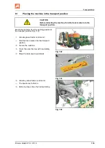
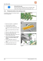
Page 119: ...he machine from the working position to the transport position Fig 112 1 Actuate green tractor control unit Fold the track marker into the transport position 2 Secure the machine 3 Cover the exact harrow with road safety bars 4 Move the ball valve to position A Fig 102 Fig 103 Fig 104 5 Activate yellow tractor control unit The booms are folded in 6 Both stop taps close the harrow folding ...

Page 120: ... such a way that you always have full control over the tractor with the attached machine In so doing take your personal abilities into account as well as the road traffic visibility and weather conditions the driving characteris tics of the driver and the mounted or attached machine WARNING Risk of contusions cutting catching drawing in and knocks through Unintentional falling of raised unsecured ...

Page 121: ...when it is being driven Instruct people to leave the danger area of the machine before switching on the universal joint shaft 10 1 Filling the seed hopper WARNING Secure the tractor machine against unintentional start up and rolling away 1 Couple the machine to the tractor 2 Climb on the loading plate via the ladder 3 Open the swivel cover 4 If necessary remove foreign bodies in the seed hopper 5 ...

Page 122: ...e exact harrow is unlocked 2 Activate yellow tractor control unit Gleichzeitig Traktorsteuergerät blau betäti gen The booms and exact harrow are folded out 3 Remove the road safety bars Fig 114 3 4 Move the stop tap to position B 5 Briefly activate yellow tractor control unit to relieve the drive wheel clamp 6 Unlock the drive wheel from the transport position see Fehler Textmarke nicht definiert ...

Page 123: ...ionally occurring ob stacles on individual coulters If the stone release is constantly reacting on all coulters ο Reduce the speed ο Reduce the placement depth ο Before seeding Till the soil to a sufficient depth During seeding Keep the stop tap Fig 90 in Position B Put the yellow tractor control unit into float position The coulters can deflect on obstacles in the soil The exact following harrow ...

Page 124: ... permissible PTO shaft speed of 1000 rpm To avoid damage only engage the PTO shaft slowly at low trac tor engine speed Only actuate the tractor control units from the tractor cabin Check the distributor heads from the tractor seat from time to time for dirt deposits Deposits of dirt and seed remains can block up the distributor heads and have to be removed immediately Normally the metering drive m...

Page 125: ...ate the yellow tractor control unit Raise the track marker 2 Actuate the yellow tractor control unit Raise the coulters exact harrows dosing is interrupted After turning 1 Actuate the yellow tractor control unit Sowing now continues 2 Actuate the green tractor control unit Lower the track marker ...

Page 126: ...inate if the metering unit is not completely emptied This can cause blocking to the rotation of the metering wheels and damage to the drive Emptying the dosing unit or hopper and dosing unit 1 Fasten the calibration trough s under the dosing unit s ο Calibration trough under the seed dos ing unit Fig 109 Fig 110 ο Calibration trough under the fertiliser dosing unit 2 Close the slide Fig 120 1 if o...

Page 127: ... them together with the dosing unit 1 Remove the metering roller see page 107 2 Close the housing cover 3 Open the seed hopper opening by slowly pulling out the shutter on the metering unit The seed drops into the calibration trough For larger quantities remove the calibration trough and allow the residues to trickle onto an underlay 4 Reassembly occurs in the reverse se quence The maintenance fla...

Page 128: ...trac tor s three point hydraulic system Unintentional falling of raised unsecured machine parts Unintentional start up and rolling away of the tractor machine combination Secure the tractor and the machine against unintentional start up and rolling away before eliminating faults on the machine See page 99 Wait for the machine to stop before entering the machine danger area ...

Page 129: ...p and rolling away before carrying out cleaning maintenance or repair work on the machine see page 99 WARNING Risk of contusions cutting catching drawing in and knocks through unprotected danger points Mount protective equipment which you removed when cleaning maintaining and repairing the machine Replace defective protective equipment with new equipment DANGER Please note the safety instructions ...

Page 130: ...ning and maintenance work Observe legal requirements when disposing of lubricants e g oils and grease Parts that come into contact with these lubri cants are also affected by these legal requirements Do not exceed a greasing pressure of 400 bar when greasing with high pressure grease guns The following are absolutely prohibited ο drilling the chassis ο enlarging pre existing drilled holes on the t...

Page 131: ...for the handling and removal of cleaning agents Cleaning with a pressure washer steam jet Always observe the following points when using a high pressure cleaner steam jet for cleaning ο Do not clean any electrical components ο Do not clean any chromed components ο Never aim the cleaning jet from the nozzle of the high pres sure cleaner steam jet directly on lubrication and bearing points ο Always ...

Page 132: ...NING The distributor head is located at the centre of the machine Apply the handbrake switch the tractor engine off and remove the ignition key Before approaching clean the path to the distributor head and the area of the distributor head danger of slippage There is the risk of an accident on the path to the distributor head and in the area of the distributor head 4 Slacken the winged nuts 1 and r...

Page 133: ...d replace it with new grease Fig 114 Lubricants For lubrication use a lithium saponified multipurpose grease with EP additives Company Lubricant designation Normal use conditions Extreme use conditions ARAL Aralub HL 2 Aralub HLP 2 FINA Marson L2 Marson EPL 2 ESSO Beacon 2 Beacon EP 2 SHELL Retinax A Tetinax AM 12 2 1 Lubrication point overview Fig 125 Lubrication point Interval Quantity 1x in the...

Page 134: ...Cleaning maintenance and repairs 134 Primera BAG0175 3 07 18 Fig 115 ...

Page 135: ...es check for wear sound condition and proper operation and replace worn parts The interior of the brake must be kept free from lubricants and dirt deposits 7 Thoroughly clean the interior and exterior of the wheel hubs Remove all traces of old grease Thoroughly clean the bearings and seals diesel oil and check for reusability Before refitting the bearings lightly grease the bearing seats and then ...

Page 136: ...ses and pipes 4 Immediately repair leaking connections After the first working run Component Maintenance work see page Specialist workshop Wheels Wheel nut check Check for play in the wheel hub bearing 146 X Fehler Textmarke nicht definiert Hydraulic system Check for defects Check for leak tightness 136 On a daily basis Component Maintenance work see page Specialist workshop Whole implement Check ...

Page 137: ...rake linkages Brake settings on the linkage adjuster 143 X Brake pad check 140 Wheels Check play on wheel hub bearings Fehler Textmarke nicht definiert X Coupling device Check the fastening bolts for wear and tight fit 145 Annually 1 000 operating hours Component Maintenance work see page Specialist workshop Brake drum Check for dirt 139 X Brake Automatic slack adjuster Functional check Brake sett...

Page 138: ... system should only be carried out by trained specialist personnel Special care is required for welding torch cutting and drill ing work in the vicinity of brake lines Always carry out a braking test after any adjustment or re pair work on the braking system General visual inspection WARNING Carry out a general visual check of the brake system Observe and check the following criteria Pipe lines ho...

Page 139: ...he wheel and brake drum must be removed Check wheel hubs bearing play To check the play on wheel hub bearings raise the axle until the wheels turn freely Release the brake Place a lever between the tyre and the ground and check the play If bearing play can be detected Adjust the bearing play 1 Remove the dust cup or hub cap 2 Remove the lynch pin from the axle nut 3 Tighten the wheel nut while tur...

Page 140: ...ntended movement Fig 119 Adjustment on linkage adjuster workshop work Move the linkage adjuster by hand in the pres sure direction If the free travel of the long stroke diaphragm cylinder pressure rod is max 35 mm the wheel brake must be readjusted Adjustments are made using the readjustment hexagon bolt on the linkage adjuster Set the free travel a to 10 12 of the connected brake lev er length B ...

Page 141: ...his should cause a smooth automat ic readjustment it should be possible to hear the coupling engaging and on the back stroke the adjusting screw should turn clockwise slightly 4 Refit the stopper cap 5 Lubricate with BPW ECO_Li91 special high melting point grease Fig 121 Air reservoir 1 Pull the drain valve Fig 136 1 in a side ways direction using the ring until no more water escapes from the air ...

Page 142: ...olts 1 2 Unscrew the bolts 2 by a few turns 3 Lift the plate 3 over the rubber seal 4 and turn to the side The unit is under spring tension 4 Remove the rubber seal Fig 123 5 Clean and grease the sealing surfaces O ring and filter Replace the rubber seal if necessary Fig 124 Correctly position the O ring on the plastic ring 6 Reassemble in the reverse sequence Bolt tightening torque 1 2 5 Nm Bolt ...

Page 143: ...0 15 bar after 10 minutes 6 Seal any leaking areas and replace leaking valves 2 Checking the pressure in the air reservoir 1 Connect a pressure gauge to the test connection on the air res ervoir Set value 6 0 to 8 1 0 2 bar 3 Checking the brake cylinder pressure 1 Connect a pressure gauge to the test connection on the brake cylinder Set value with brake not applied 0 0 bar 4 Visual inspection of t...

Page 144: ...ired to firmly apply the parking brake if you have just fitted new brake pads Adjusting the parking brake When the parking brake is off the brake cable must hang slightly slack However the brake cable must not rest on or chafe against other parts of the vehicle 1 Release the cable clamps 2 Shorten the brake cable as appropriate and retighten the cable clamps 3 Check for the correct braking effect ...

Page 145: ...ion Fixing bolts Number Tightening torque Lower link trav erse Cat 3 34 5 mm Cat 4 48 0 mm Cat 5 56 0 mm M20 8 8 8 410 Nm Ball coupling K80 LI009 82 mm M16 10 9 8 300 Nm K80 LI040 82 mm M20 10 9 8 560 Nm K80 LI015 82 mm M20 10 9 12 560 Nm Drawbar eye D35 LI038 36 5 mm M16 12 9 6 340 Nm D40 LI017 41 5 mm M16 10 9 6 300 Nm D40 LI006 42 5 mm M20 8 8 8 395 Nm D46 LI034 48 mm M20 10 9 12 550 Nm D50 LI0...

Page 146: ...s ing suitable assembly tools Tyre fitting requires sufficient skills and proper assembly tools Use the jack only at the jacking points indicated 12 7 1 Tyre pressures The required tyre pressure is dependent on ο tyre size ο tyre loading capacity ο the travel speed The operational performance of the tyres is reduced ο by overloading ο if the tyre pressure is too low ο if the tyre pressure is too h...

Page 147: ...orrosion from the wheel rim seating sur faces before fitting a new another tyre Corrosion can cause damage to the wheel rims when the vehicle is in operation When fitting new tyres always use new valves for tubeless tyres or new inner tubes Always fit the valves with valve caps which have a gasket insert ...

Page 148: ...he trailer Ensure that the hydraulic hose lines are connected correctly Regularly check all the hydraulic hose lines and couplings for damage and impurities Have the hydraulic hose line checked at least once a year by a specialist for proper functioning Replace the hydraulic hose line if it is damaged or worn Only use AMAZONE original hydraulic hose lines The hydraulic hose lines should not be use...

Page 149: ...maged hydraulic hose lines immediately 12 8 3 Inspection criteria for hydraulic hose lines For your own safety comply with the following inspection criteria Replace hoses if the respective hose fulfils at least one of the follow ing criteria Damage to the outer layer up to the ply e g scouring points cuts cracks Brittleness of the outer layer crack formation of the hose mate rial Deformations whic...

Page 150: ...ration ο There is no tension apart from the hose s own weight ο There is no possibility of jolting on short lengths ο Outer mechanical influences on the hydraulic hose lines are avoided Use appropriate arrangements and fixing to prevent any scouring of the hoses on components or on each other If necessary secure hydraulic hose lines using protective co vers Cover sharp edged components ο The appro...

Page 151: ... at least 35 li tres 2 Release and remove the oil dipstick 1 3 Undo the drain plug Old oil flows out of the oil tank 4 Check the seal on the drain plug and re place if necessary 5 Retighten the drain plug 6 Loosen the 3 screws on the oil filter 1 replace the oil filter insert 7 Fill the oil via the opening for the oil dipstick 8 Screw the oil dipstick and seal back in and check the oil level Fig 1...

Page 152: ...To remove the filter twist off the filter cover and remove the filter After replacing the filter press the contamination indicator back into place Fig 130 On board hydraulic system oil filter with contam ination level indicator 12 10 Upper and lower link pins WARNING Risk of contusions catching and knocks when the machine unexpectedly releases from the tractor Check the upper and lower link pins f...

Page 153: ... 11 Setting the tramline to the tractor s track spacing specialist workshop The seed hoses are numbered Standard seed hoses which are switched off when creating tramlines Alternative adjustable seed hoses for tramlines Row spacing 18 75 cm Row spacing 25 cm Fig 131 ...

Page 154: ... the tramline control is properly set for the track width of the cultivating tractor The seed line tubes 1 of the tramline coul ters must be attached to the distributor head openings which can be closed by the shutters 2 If necessary interchange the seed line tubes The wheelmark width changes with the number of coulters that do not spread seed when the tramlines are created To create two tracks it...

Page 155: ...tributor head is located at the centre of the machine Securing the tractor machine against unintentional start up and rolling away Before approaching clean the path to the distributor head and the area of the distributor head danger of slippage There is the risk of an accident on the path to the distributor head and in the area of the distributor head Activating or deactivating sliders 1 Remove th...

Page 156: ...d repairs 156 Primera BAG0175 3 07 18 10 Install the foam insert 1 11 Install the inner distributor cover 2 12 Install the ring 3 13 Install the outer distributor cover 4 14 Check the function of the tramline circuit Fig 135 ...

Page 157: ...Cleaning maintenance and repairs Primera BAG0175 3 07 18 157 12 12 Hydraulics diagram ...

Page 158: ...Cleaning maintenance and repairs 158 Primera BAG0175 3 07 18 Hydraulic brake Fig 136 ...

Page 159: ...Cleaning maintenance and repairs Primera BAG0175 3 07 18 159 On board hydraulic system Filling auger ...

Page 160: ...Cleaning maintenance and repairs 160 Primera BAG0175 3 07 18 Fan hydraulic system ...

Page 161: ... M 14x1 5 150 210 250 M 16 24 210 300 355 M 16x1 5 225 315 380 M 18 27 290 405 485 M 18x1 5 325 460 550 M 20 30 410 580 690 M 20x1 5 460 640 770 M 22 32 550 780 930 M 22x1 5 610 860 1050 M 24 36 710 1000 1200 M 24x2 780 1100 1300 M 27 41 1050 1500 1800 M 27x2 1150 1600 1950 M 30 46 1450 2000 2400 M 30x2 1600 2250 2700 M M4 M5 M6 M8 M10 M12 M14 M16 M18 M20 M22 M24 2 3 4 6 7 9 19 3 39 66 106 162 232...

Page 162: ......
Reviews: