background image


General description of the machine 


PROFIHOPPER  BAF0012.6  04.18


31 


3.5.1 

Noise production data 


The emission value (noise level) applicable to the working area is:  
LpA = 90 dB(A). Measurements were taken under working conditions 
close to the driver's ear. Noise level in accordance with Decree 
2000/14/CE: LwA = 105 dB(A). 


Comply with EC Noise-at-Work Directive (2003/10/EEC) and the 
German "Occupational Health and Safety Ordinance on Noise and 
Vibration"


DANGER: 

The running drive motor and mower drive cause noise pollution. If 
there is excessive exposure, noise can permanently impair hearing. 

Wear hearing protection! 

Recommended hearing protection: 

MOLDEX Comets® 6420  

(Tested and approved in accordance with EN 352-2:2002) 

3.5.2 

Vibration data 


- Hand-, Arm- and complete Body vibrations measured according to  
  EN 12096:  

(a) Levering machine :  
 

left-hand side 2.18 m/s² (measurement

 accuracy 0,08 m/s²) 


right-hand side 1.72 m/s² (measurement

 accuracy 0,11 m/s²) 


complete body 0.34 m/s² (measurement

 accuracy 0,03 m/s²) 

(b) Steering wheel machine:  
 

left hand 0.88 m/s² (measurement

 accuracy 0,01 m/s²) ,  


right hand 1.61 m/s² (measurement

 accuracy 0,12 m/s) 


complete body 0.33 m/s² (measurement

 accuracy 0,05 m/s²) 


Summary of Contents for PH-1250 iDrive

Page 1: ...FIHOPPER PH 1250 zDrive PH 1250 iDrive PH 1250 4WDi MG5087 BAF0012 6 04 18 Printed in France Read and observe this operat ing manual before putting the equipment into operation for the first time Keep in a safe place for future reference en ...

Page 2: ...he person concerned would not only harm himself but also make the mistake of blaming the machine for the reason of a possible failure instead of himself In order to ensure good success one should go into the mind of a thing make himself familiar with every part of the machine and to get acquainted with its handling Only in this way would you be satisfied both with the machine as also with yourself...

Page 3: ...ORBACH 17 rue de la Verrerie BP 90106 F 57602 Phone Fax E mail Forbach France 33 0 3 87 84 65 70 33 0 3 87 84 65 71 forbach amazone fr Spare part orders Spare parts lists are freely accessible in the spare parts portal at www amazone de Please send orders to your AMAZONE dealer Formalities of the operating manual Document number MG5087 Compilation date 11 17 Copyright AMAZONEN WERKE H DREYER GmbH ...

Page 4: ...peration Only after careful reading will you be able to benefit from the full scope of your newly pur chased machine Please ensure that all the machine operators have read this operating manual before they put the machine into operation Should you have any questions or problems please consult this op erating manual or contact your local service partner Regular maintenance and timely replacement of...

Page 5: ...formation is not observed 24 2 15 Safety conscious working 24 2 16 Safety information for users 25 2 16 1 General safety and accident prevention information 25 2 16 2 Hydraulic system 26 2 16 3 Electrical system 27 2 16 4 Safety check before moving off 28 3 General description of the machine 29 3 1 Areas of application 29 3 2 Declaration of conformity 29 3 3 Details required for enquiries 29 3 4 R...

Page 6: ...0 1 Seat contact switch defective 71 10 2 Towing the machine 72 11 Maintenance 73 11 1 Cleaning 73 11 2 Maintenance control lamp 73 11 3 Rotor condition 74 11 4 Engine maintenance 74 11 4 1 Oil level oil change 75 11 4 2 Engine oil filter 75 11 4 3 Air filter 75 11 4 4 Fuel filter 76 11 4 5 Cooling system 77 11 4 6 Power transmission belts 78 11 5 Hydrostatic drive 79 11 5 1 Hydraulic oil cooling ...

Page 7: ...d in the operating manual are always viewed in the direction of travel 1 3 Diagrams used Instructions for action and reactions Tasks to be carried out by the user are presented as numbered instruc tions Always keep to the order of the instructions The reaction to instruc tions is given by an arrow Example 1 Instruction for action 1 Reaction of the machine to instruction for action 1 2 Instruction ...

Page 8: ...ate To replace damaged warning symbols If you still have queries please contact the manufacturer Obligations of the user Before starting work anyone charged with working with on the machine is obliged To comply with the basic workplace safety instructions and accident prevention regulations To read and understand the section General safety information of this operating manual To read the section W...

Page 9: ...e shall be available to the operator at the latest on the completion of the contract Guarantee and liability claims for damage to people or goods will be excluded if they can be traced back to one or more of the following causes Improper use of the machine Improper installation commissioning operation and maintenance of the machine Operation of the machine with defective safety equipment or im pro...

Page 10: ...immediate death or serious physical injury WARNING Indicates a medium risk which could result in death or extremely serious physical injury if not avoided If the instructions are not followed then this may result in death or serious physical injury CAUTION Indicates a low risk which could incur minor or medium level physi cal injury or damage to property if not avoided IMPORTANT Indicates an oblig...

Page 11: ...ent regularly 2 4 Safety and protection equipment Before each commissioning of the machine all the safety and protection equipment must be properly attached and fully functional Check all the safety and protection equipment regularly Faulty safety equipment Faulty or disassembled safety and protection equipment can lead to dan gerous situations 2 5 Informal safety measures As well as all the safet...

Page 12: ...Instructed persons are those who have been instructed in their as signed tasks and in the possible risks in the case of improper be haviour have been trained if necessary and have been informed about the necessary protective equipment and measures 3 People with specialist technical training shall be considered as a specialist Due to their specialist training and their knowledge of the appropriate ...

Page 13: ...rrying out replacement work Check all the screw connections for a firm seat On completing mainte nance work check the function of safety and protection equipment 2 10 Constructive changes You may make no changes expansions or modifications to the machine without the authorisation of AMAZONEN WERKE This is also valid when welding support parts Any expansion or modification work shall require the wr...

Page 14: ...ear and spare parts from third parties there is no guarantee that they have been designed and manufactured in such a way as to meet the requirements placed on them AMAZONEN WERKE accepts no liability for damage arising from the use of unapproved spare parts wear parts or auxiliary materials 2 11 Cleaning and disposal Handle and dispose of any materials used carefully in particular When carrying ou...

Page 15: ...ions PROFIHOPPER BAF0012 6 04 18 15 2 13 Warning symbols and other signs on the machine 2 13 1 Positioning of warning symbols and other labels The following diagrams show the arrangement of the warning symbols on the machine ...

Page 16: ...6 PROFIHOPPER BAF0012 6 04 18 Always keep all the warning symbols of the machine clean and in a legi ble state Replace illegible warning symbols You can obtain the warning symbols from your dealer using the order number e g MD 075 ...

Page 17: ...l showing how to avoid the danger Warning symbols explanation The column Order number and explanation provides an explanation of the neighbouring warning symbol The description of the warning symbols is always the same and specifies in the following order 1 A description of the danger For example danger of cutting 2 The consequence of non observance of the danger protection in structions For examp...

Page 18: ... hands or arms Never open or remove protective equipment from chains or belt drives while the tractor engine is running and the PTO shaft is connected hydraulic drive is en gaged or the ground wheel drive is in motion MD 078 Risk of fingers or hands being crushed by ac cessible moving machine parts This hazard can cause extremely serious injuries with the loss of body parts such as fingers or hand...

Page 19: ...pen or remove guard devices from moving machine parts while the tractor engine is running with the PTO shaft connected hydraulic drive en gaged MD 084 Risk of contusions over the whole body from machine parts moving down from above This hazard can cause extremely serious injuries anywhere on the body or even death It is forbidden to stand in the swivel area of moving machine parts Instruct people ...

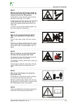
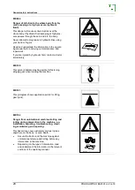
Page 20: ...by hydraulic fluid contact a doctor immediately MD 100 This symbol indicates lashing points for fastening slinging gear when loading the machine MD 101 This pictogram shows application points for lifting gear jack MD 102 Danger from unintentional machine starting and rolling during intervention in the machine e g installation adjusting troubleshooting clean ing maintaining and repairing This hazar...

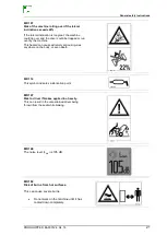
Page 21: ...by the machine This hazard can cause extremely serious injuries anywhere on the body or even death MD 114 This symbol indicates a lubrication point MD 147 Risk to driver if brakes applied too heavily This can result in the unrestrained driver being thrown from the seat while braking MD 148 The noise level LWA is 105 dB MD 182 Risk of burns from hot surfaces This can cause severe burns Do not work ...

Page 22: ...ystem is 210 bar MD 202 Placing the transport safeguard This danger can result in machine parts getting lost during transport and posing significant haz ards for road traffic Danger of fatal injury in public road traffic Prior to transporting the machine on a trailer or on an open load surface the locking mechanisms must be firmly closed via the rubber strap Open the rubber element for work de plo...

Page 23: ...ns PROFIHOPPER BAF0012 6 04 18 23 MD 231 Driving across the slope up to max 22 Use roll over protection Attach seat belt To pass through low clearance height on level ground Fold in roll over protection Do not put on seat belt ...

Page 24: ...ough non secured working areas Failure of important machine functions Failure of prescribed methods of maintenance and repair Danger to people through mechanical and chemical impacts Risk to environment through leakage of hydraulic fluid 2 15 Safety conscious working Besides the safety information in this operating manual the national gen eral workplace safety and accident prevention regulations a...

Page 25: ... of the machine into account Use of the machine Before starting work ensure that you understand all the equipment and actuation elements of the machine and their function There is no time for this when the machine is already in operation Do not wear loose fitting clothing Loose clothing increases the risk over being caught by drive shafts Only start up the machine when all the safety equipment has...

Page 26: ...ator controls which are used for hy draulic and electrical movements of components e g folding swiv elling and pushing movements The movement must stop automati cally when you release the appropriate control This does not apply to equipment movements that ο are continuous or ο are automatically locked or ο necessarily require an open centre or pressure position to oper ate correctly Before working...

Page 27: ...When dis connecting the battery disconnect the negative terminal first fol lowed by the positive terminal Always place the appropriate cover over the positive battery terminal Contact with earth may cause an explosion Risk of explosion avoid the production of sparks or the presence of naked flames in the vicinity of the battery The machine can be equipped with electronic components and units whose...

Page 28: ...ompo nents each time before you move off Tyre pressure and tread condition Seat switch operation Oil and hydraulic lines for leaks and or porosity Blade and blade mounts for loose screws and severe wear Check safety devices for loose screws or mounts Hopper lid must be closed Check mulcher flap is in place The mower unit must switch off as soon as the hopper is raised ...

Page 29: ... always specify the machine number when ordering special optional equipment and spare parts or when making technical enquir ies Safety requirements are only fulfilled if genuine AMAZONE spare parts are used when a repair is undertaken The use of other parts may remove liability for any consequences which may occur as a result 3 4 Rating plate and CE marking The rating plate shows Vehicle machine I...

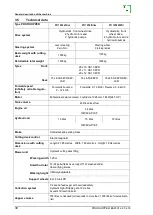
Page 30: ...reverse 0 12 km h Forwards 0 12km h Reverse 0 6km h Motor Kohler diesel water cooled 3 cylinders 1028 ccm 18kW 24 5 HP Tank volume 40 litres diesel fuel Engine oil 3 4 litres 10W40 API CF Hydraulic oil 15 litres 15 litres 18 litres 10W40 API CF Brake Hydrostatic and parking brake Cutting deck control Electromagnetic Dimensions with cutting deck Length 2 785 metres Width 1 482 metres Height 1 994 m...

Page 31: ...ower drive cause noise pollution If there is excessive exposure noise can permanently impair hearing Wear hearing protection Recommended hearing protection MOLDEX Comets 6420 Tested and approved in accordance with EN 352 2 2002 3 5 2 Vibration data Hand Arm and complete Body vibrations measured according to EN 12096 a Levering machine left hand side 2 18 m s measurement accuracy 0 08 m s right han...

Page 32: ... the pump 1 During operation with lowered cutting deck in float position 2 With raised cutting deck 3 Turning with raised cutting deck 1 2 3 Across a slope 22 12 22 12 18 10 Uphill downhill 27 15 18 10 18 10 On slopes the motor must be operated at full throttle to prevent Intended use also covers observing all of the instructions in this operating manual execution of inspection and maintenance wor...

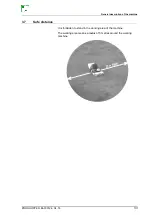
Page 33: ...l description of the machine PROFIHOPPER BAF0012 6 04 18 33 3 7 Safe distance It is forbidden to stand in the working area of the machine The working area means a radius of 5 metres around the working machine ...

Page 34: ...r HGV CAUTION The machine must always be loaded or driven in straight ahead direction of travel 3 For transport on a trailer the machine must be firmly lashed the parking brake must be engaged and the motor switched off Comply with the specified lashing points Lash the machine on the transport vehicle as prescribed Lash diagonally in accordance with DIN EN121951 At least 4 lashing elements must be...

Page 35: ... hopper must always be completely emptied Fermenting mowed material can auto ignite under certain conditions due to the the significant heat development 6 Danger of damaging the drive system Do not push the machine if the motor is switched off The fastening on the hood must be fixed tight Ensure that the cover of the hopper is adequately secured CAUTION A strong headwind can cause the hood to brea...

Page 36: ... or if parts are missing Replacements will only be made if claims are submitted promptly to the haulage company Please check that all the parts listed on the despatch note have been delivered Any damage must be noted on the delivery note immediately in the pres ence of the driver Before starting up completely remove all packaging including wires and check lubrication ...

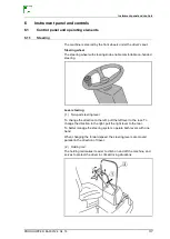
Page 37: ...steering Lever steering 1 Two part steering lever To change the direction to the left pull the left lever to the rear To change the direction to the right pull the right lever to the rear To better manage the steering system operate both levers with one hand When changing the forward speed the steering levers are moved parallel in the direction of travel 2 Holding rail The holding rail makes it ea...

Page 38: ...ain the engine is automatically switched off Check the coolant level and refill if necessary Check the guard screen and radiator for contamination and clean if necessary If the warning lamp is not turned off when the engine is started again or if the engine overheats again contact your service partner 6 Warning indicator Flashes when the implement is in a safety critical state 7 Parking brake cont...

Page 39: ...en the hopper is accidentally raised during operation The hopper must then be moved to working position the engine restarted and the mower unit switched on again 15 Parking lights 16 Warning flasher 17 Dipped beam 18 Cooling water temperature display Green light Cooling water temperature is normal Red flashing light Motor is overheating 19 Operating hours counter 20 Ignition key position Engine of...

Page 40: ...ting the cutting deck Pull the lever to the rear Lowering the cutting deck Push the lever to the front Locking the cutting deck at the bottom in float position The cutting deck can then adapt to ground undulations 5 Switching on the cutting deck To start running the cutting deck more smoothly select a mod erate engine speed Briefly press the start switch to start the cut ting deck until the cuttin...

Page 41: ...ed with the aid of the ignition key For this purpose place the head of the key on the slotted screwdriver and turn to the right by less than 45 The mechani cal lock is therefore open and the seat support can be opened upwards using the handle Only open the hood when the engine is switched off CAUTION Drive very carefully when the hopper is raised Risk of tipping ...

Page 42: ...oving the foot from the pedal pushing the pe dal in the opposite direction Abrupt actuation of the accelerator pedal causes strong acceleration of the machine or sudden standstill Familiarise yourself with the driving behaviour of the machine in an open area and at moderate speeds Risk of accident 1 Parking brake pedal 2 Parking brake locking mechanism 3 Accelerator pedal The accelerator pedal is ...

Page 43: ...re quickly Parking brake When the parking brake is applied the accelerator pedal is blocked Thanks to an additional circuit the driver can leave the driver s seat when the parking brake is applied and the cutting deck is switched off without the engine switching itself off This prevents constant restarting of the engine after leaving the seat This protects the engine starter and battery Securing t...

Page 44: ...jump off in case the machine tips This is only allowed on level ground Fold the roll over protection back up again immediately after passing the obstacle and fasten the seat belt Putting the roll over protection into operation out of operation 1 Lift the catch and insert the safety supports 2 Remove the positioning pins 3 Fold the roll over protection down up 4 Fix the roll over protection with th...

Page 45: ...Harte Federung Hebel heben und nach links drehen Sicherheitsgurt Der Sitz verfügt über einen Sicherheitsgurt Bei aufrechtem Überrollschutz stets einen Sicherheitsgurt anlegen Nicht von umkippenden Maschinen springen ο Beide Enden des Sicherheitsgurts anschließen ο Den Sicherheitsgurt straffen oder lösen bis er fest am Kör per anliegt ο Den roten Knopf an der Schnalle drücken um den Sicher heitsgur...

Page 46: ...3 2 Deluxe driver s seat Grammer seat with air suspension and heater 1 Handle for horizontal adjustment 2 Handle for weight adjustment 3 Handle for backrest adjustment 4 Hand wheel for armrest tilt adjustment 5 Switch for seat heater 6 Hand wheel for lumbar support ...

Page 47: ...tem for removing plant material blocking the radiator grill especially when mulching The self cleaning system contains a controller an extra cleaning fan an electromagnetic clutch for the engine fan Operation The main air flow is partly interrupt ed and reversed by the additional fan This frees the grill of plant ma terial and dirt Fig 9 3 1 The main cooling air flow is restored to the radiator Fi...

Page 48: ...ion 9 2 3 A safety switch under the seat for switching off the engine as soon as the driver leaves the seat and the parking brake is not engaged One on the hopper to switch off the engine if the hopper is raised while the mower unit is still in operation A safety switch on the hopper cover for switching off the cutting deck once the grass box has been filled completely Fig 7 1 1 One under the mowe...

Page 49: ...FIHOPPER BAF0012 6 04 18 49 7 2 Tyre pressure Always inflate the tyres to the specified pressure Pressures other than those recommended may impair driving characteristics Tyre pressure front 1 5 bar rear 1 5 bar Mower unit tyres 1 5 bar ...

Page 50: ... necessary Fig 7 3 2 Oil grade 10W40 API CF diesel engine oil Total filling amount 3 4l Hydrostat hydraulic fluid The oil tank is integrated into the frame and is located on the left side of the machine The red lines indicate the minimum and maximum oil levels Check the oil level and top up if necessary Fig 7 3 3 Remember that oil expands when it is hot Do not overfill ...

Page 51: ...OPPER BAF0012 6 04 18 51 Fuel diesel The fuel tank is on the right side of the machine It is easy to access Opening the screw connection and folding down the protective grille Fig 7 3 4 Filling the tank through by opening the cap Fig 7 3 5 ...

Page 52: ...uel according the norm ISO 8217 DMX or EN590 96 only The use of another fuel e g biodiesel RME or another fuel mixture will make the engine inoperable Diesel tank capacity 40 l Diesel consumption 3 4 l per hour DIESEL catches fire easily Fire naked flames and smoking are for bidden near diesel Prevent diesel from coming into contact with your bare skin Breathing in diesel fumes is hazardous for yo...

Page 53: ...ng Move the accelerator lever no further than the centre position Do not interrupt the starting procedure but do not try to start the engine for more than 5 seconds at a time CAUTION Never start the engine in an enclosed space There is a risk of asphyxiation To switch off the engine proceed as follows 1 Bring the machine to a stop 2 Move the accelerator lever back to the idle position 3 Apply the ...

Page 54: ...ansport Abrupt actuation of the accelerator pedal causes unexpected strong acceleration or deceleration On slopes the motor must be operated at full throttle to prevent cavitation damage to the pump 1 Attach seat belt 2 Disengage parking brake 3 Increase engine speed 4 Drive off carefully actuate accelerator pedal 5 Check the steering 6 While driving set the maximum engine speed ...

Page 55: ...e with EN 352 2 2002 Abrupt actuation of the accelerator pedal causes unexpected strong acceleration or deceleration WARNING Danger of being entangled and drawn in and danger from foreign objects being caught and thrown in the danger area of the driven cut ting deck It is forbidden to drive with the cutting deck cover folded open It is forbidden to switch on the cutting deck when the cutting deck ...

Page 56: ...on the foot throttle until you have reached the de sired driving speed Adapt the driving speed to the mowing conditions After finishing work 9 Stop the cutting deck drive 10 Lift the cutting deck During operation check the cooling air grid for contamination and plant residues ...

Page 57: ... position when it is empty by push ing the lever forward Emptying from a height 1 Back the machine to within about 1 m of the discharge point 2 Use the control lever to bring the hopper to the correct discharge height 3 Slowly back towards the discharge point Fig 8 7 4 Tip the hopper 5 Swing the hopper back to its original position 6 Move forwards to about 1 m from the discharge point 7 Lower the ...

Page 58: ...lade overview A B C D E Blade replacement without tools Wing blade long H77 sharpened standard Scarifying blade 3 mm Scarifying blade 2 mm Wing blade long H77 sharpened with scarifying blade Wing blade sharpened with scarifying blade Lawn Golf course Park Public green spaces Cutting flowers and eco meadows Foliage collection Scarifying Scarifying golf courses bowling greens Weeding lawns Paddocks ...

Page 59: ...is fitted with 36 pairs of wing blades as standard 9 pairs blades x 4 rows 36 pairs blades rotor SCARIFYING The Profihopper can be used to scarify the lawn and collect the scarified material as it goes 9 blades x 4 rows 36 blades rotor NOTE Only one type of scarifying blade may be used at a time 2mm OR 3mm Risk of imbalance Direction of travel Direction of travel ...

Page 60: ...g the blades on the clip bolts WING BLADES LONG H77 Operational area Lawn Golf course Park Public green spaces Cutting flowers and eco meadows Foliage collection mulch SCARIFYING BLADES Operational area 2mm Scarifying 3mm Scarifying golf courses bowling greens WING BLADES LONG H77 WITH SCARIFYING BLADES Operational area Foliage collection Paddocks mulch ...

Page 61: ...ing lawns MOWING BLADES Y SHAPED Operational area Mulch ONLY These require less power from the machine but are re stricted in their collection capabilities NOTE It is essential for the rotor to be equipped with one of the above blade arrangements If mower tools are missing or have been incor rectly fitted an imbalance is created which over time will lead to the whole machine being damaged ...

Page 62: ...and clip bolts must be checked regularly for wear Heavily worn tools must be promptly replaced Figs 8 1 2 and 8 1 3 show the limits of wear for the mounting brackets CAUTION The blades and the blade fasteners must be checked before the start of every run All screw unions must be firmly tightened new used new used ...

Page 63: ...o improve cut quality when mowing The baffle plate is set for scarifying at the factory Setting options Scarifying push the plate forwards to the stop Mowing push the plate back to the stop The plate must be in the forward position when scarifying Four bolts Fig 8 2 2 need to be undone to slide the bar You can use a hammer to tap the plate towards the rotor Fig 8 2 3 front rear ...

Page 64: ...djusting the cutting height To adjust the cutting height proceed as follows Open the retaining hook and remove the crank handle Fig 8 3 1 Turn the lever Fig 8 3 2 Turn to set the desired cutting height Fig 8 3 3 Return the lever to the locked position and fix in holder ...

Page 65: ...Cutting scarifying and mulching PROFIHOPPER BAF0012 6 04 18 65 The mower unit has a cutting height gauge ...

Page 66: ...ting scarifying and mulching 66 PROFIHOPPER BAF0012 6 04 18 CAUTION The lever must be returned to the locked position To do so turn the lever place it on the pin and lock with the retain ing hook Fig 8 3 4 ...

Page 67: ...o the overload clutch The warning light on the instrument panel also comes on Switch off the mower unit as quickly as possible ATTENTION After the period from the shutdown of the engine to a complete stop of the rotor is ca 5 seconds The mowers may only be opened when the rotor hibernation has been achieved Clean the worm conveyors as follows Cleaning the transverse worm 1 Switch off the mower uni...

Page 68: ...ver on the belt guard Fig 8 4 3 2 Insert the crank handle over the end of the transverse worm conveyor Fig 8 4 4 3 Release the foreign matter by turning the worm and remove Cleaning the longitudinal worm Raise the hopper to the highest position Support it with the safety bracket Fig 8 4 5 ...

Page 69: ...pper from lowering accidentally Release the foreign matter by turning the worm and remove Fig 8 4 6 Remove the safety bracket Lower the hopper into the working position Close and lock the mower unit cover CAUTION Before restarting the mower unit make sure the cover is firmly locked in place If the lock bolts are faulty replace them immediate ly You can now continue working ...

Page 70: ...omes with an attachment that allows you to mow and mulch the cut grass without collecting it To do so take the mulch flap from the cover and place it in the rotor box Fig 5 5 This stops the cuttings entering the transverse worm Instead they are mulched and returned directly to the ground ...

Page 71: ...fitted next to the driver s seat 10 Faults 10 1 Seat contact switch defective Seat contact switch defective control lamp As soon as the parking brake is released the engine is switched off Driving the machine with a defective seat contact switch 1 Apply the parking brake 2 Start the engine 3 Move the catch into working position 4 Press and hold the Cutting deck on switch 5 Press the Cutting deck o...

Page 72: ...e there can be damage to the machine Close the bypass against before operation iDrive 4WDi Open the bypass of the hydraulic pumps using the hand lever Close the bypass again before operation 1 Hand lever in towing position 2 Hand lever in operating position zDrive Open the bypass of the hydraulic pumps by loosening the adjusting screw by one turn To tow the machine use the two attachment points fo...

Page 73: ...cleaner During the cleaning procedure remove the ignition key and seal the ignition lock with the protective dust cap 1 Open the mower unit cover 2 Clean the rotor box with a high pressure hose After cleaning the dirty water must flow away completely from the worm conveyor system 3 Clear the drain holes underneath the feeder tube for the longitu dinal worm 4 Clean the radiator with compressed air ...

Page 74: ...low the operating and maintenance instructions in the LOMBARDINI operating instructions These instructions are supplied with the machine CAUTION Make sure you read the LOMBARDINI operating instructions careful ly before starting the machine for the first time CAUTION Before working on any parts connected to the engine switch off the engine remove the ignition key and allow the engine to cool down ...

Page 75: ...ngine operating instructions 11 4 3 Air filter Clean the air filter with compressed air at least once a week If conditions are dry and dusty clean the filter daily Replace faulty filter cartridges immediately To remove the air filter proceed as follows Open both retaining clips Remove the cover Remove the cartridges 2 filters inside each other Fig 10 3 3 1 ...

Page 76: ...erse order Fig 10 3 3 2 The air filter has a pre filter that must be cleaned each day Remove the wing nut Take off the seal Clean the dust catcher Fig 10 3 3 3 Reverse the above order to refit the pre filter 11 4 4 Fuel filter The fuel filter should be replaced every 250 operating hours or at least once per year For more details see the LOMBARDINI operating instructions ...

Page 77: ...ion tank This does not prevent overheating but ensures that the overheated water can con dense and be returned to the system The fluid level in the expansion tank should be checked daily Refill the radiator if the coolant circuit is empty To do so Undo and remove the radiator cover Fig 10 3 5 2 1 Fill the radiator to the lip with coolant Fig 10 3 5 2 2 then refit the cover Open the expansion tank ...

Page 78: ...tenance 78 PROFIHOPPER BAF0012 6 04 18 Fig 10 3 5 1 The coolant level should be checked weekly The coolant remains liquid to 30 C 11 4 6 Power transmission belts See LOMBARDINI engine operating instructions ...

Page 79: ...ieve 3 Fill level indicator 11 6 Battery Charging the battery Refer to the charger operating manual Detach and remove the battery before charging Disconnecting the battery Do not disconnect the terminal clamps until the engine has stopped Switch off electrical consumers Undo and remove the negative and positive leads in that order Reconnecting the battery Connect the positive and then the negative...

Page 80: ...away splashed acid with clear fresh water Consult a doctor if necessary Protect eyes and face Keep children well away The DELCO FREEDOM PLUS battery has a HYDROMETER for fast and simple checking of the battery charge level Green display Battery is sufficiently charged more than 65 Black display Battery is not sufficiently charged less than 65 The battery must be recharged Pale display The electrol...

Page 81: ...s are located in the electric switch box under the seat support Undo the two screws to open the box Replacement fuses can be found in the accessories kit under the seat support Elimi nate the cause of the fuse melting in all cases Fuses F1 F10 15 A Fuse F11 20 A Fuse F12 40 A Relays K1 K8 ...

Page 82: ...regularly or every time the machine is thoroughly cleaned in order to keep your Amazone Profihop per working in top condition 11 8 1 Running gear Main drive shaft Main drive shaft bearings Fig 10 6 1 1 Every 50 operating hours 2 pump strokes Controls Control lever linkages Fig 10 6 1 2 Links of the foot throttle ...

Page 83: ...ery 150 operating hours only Fig 10 6 2 1 CAUTION Excess grease can easily reach the lower protection plate on the belt drives and damage it Fig 10 6 2 2 Front wheel fork bearings Fig 10 6 2 3 1 Support bracket linkage Fig 10 6 2 3 2 Rear cage roller bearing Fig 10 6 2 3 3 Connecting arm bearing Fig 10 6 2 4 and Fig 10 6 2 5 ...

Page 84: ...Maintenance 84 PROFIHOPPER BAF0012 6 04 18 ...

Page 85: ...Maintenance PROFIHOPPER BAF0012 6 04 18 85 Mower unit drive shaft bearing Fig 10 6 2 6 and Fig 10 6 2 7 There are 2 lubrication nipples of the drive shaft bearings ...

Page 86: ...Maintenance 86 PROFIHOPPER BAF0012 6 04 18 Longitudinal worm drive shaft bearings Fig 10 6 2 8 Longitudinal work drive cross linkage Fig 10 6 2 9 ...

Page 87: ...Maintenance PROFIHOPPER BAF0012 6 04 18 87 Transverse worm bearings Fig 10 6 2 10 Fig 10 6 2 11 Rotor bearings Fig 10 6 2 11 Fig 10 6 2 12 b trans verse worm bearing a rotor ...

Page 88: ...Maintenance 88 PROFIHOPPER BAF0012 6 04 18 Height adjustment Fig 10 6 2 13 ...

Page 89: ...installation After running in Fan drive 1 250 N 300 N 200 N 350 N 156 Hz 171 Hz 140 Hz 156 Hz Main drive 2 380 N 430 N 330 N 380 N 97 Hz 103 Hz 91 Hz 97 Hz Mower unit drive 2 380 N 430 N 330 N 380 N 57 Hz 61 Hz 53 Hz 57 Hz Rotor drive 5 380 N 430 N 330 N 380 N 167 Hz 177 Hz 155 Hz 167 Hz Longitudinal worm drive 3 380 N 430 N 330 N 380 N 254 Hz 270 Hz 237 Hz 254 Hz Natural frequency of the greatest...

Page 90: ...oroughly Carry out all lubrication Empty the fuel tank Disconnect the battery see 10 5 Store the battery in a dry cool and frost free place Check the condition of the V belts Contact Service if they need replacing Make sure there is sufficient antifreeze in the cooling system Store the machine in a dry place ...

Page 91: ...Maintenance PROFIHOPPER BAF0012 6 04 18 91 11 11 Maintenance plan ...

Page 92: ...ir filter x2 Fuel filter Other __________________________________ Next service on __________________________ Dealer stamp and signature MAINTENANCE REPORT Date ________ Mechanic __________________ Report no _______________________________ Operating hours __________________________ YES NO Engine oil change Hydraulic oil change Engine oil filter Hydraulic oil filter Air filter x2 Fuel filter Other _...

Page 93: ... Fuel filter Other _________________________________ Next service on __________________________ Dealer stamp and signature MAINTENANCE REPORT Date _________Mechanic _________________ Report no _______________________________ Operating hours __________________________ YES NO Engine oil change Hydraulic oil change Engine oil filter Hydraulic oil filter Air filter x2 Fuel filter Other _______________...

Page 94: ...Fuel filter Other __________________________________ Next service on __________________________ Dealer stamp and signature MAINTENANCE REPORT Date ________ Mechanic __________________ Report no _______________________________ Operating hours __________________________ YES NO Engine oil change Hydraulic oil change Engine oil filter Hydraulic oil filter Air filter x2 Fuel filter Other ______________...

Page 95: ... Fuel filter Other _________________________________ Next service on __________________________ Dealer stamp and signature MAINTENANCE REPORT Date _________Mechanic _________________ Report no _______________________________ Operating hours __________________________ YES NO Engine oil change Hydraulic oil change Engine oil filter Hydraulic oil filter Air filter x2 Fuel filter Other _______________...

Page 96: ......

Reviews: