Copyright 2018 by Amber Kinetics. All rights reserved.
6
M32 FLYWHEEL - INSTALLATION & MAINTENANCE MANUAL
1.3 - M32 Flywheel Description
The Flywheel Module (FM) consists of the Flywheel
Housing that contains the primary electric and
mechanical components of the M32 flywheel, an
Electronics Enclosure mounted on the top of the
Flywheel Housing, and a Passive Vacuum Pump that is
also mounted to the Flywheel Housing.
This assembly functions as a “mechanical battery.”
Like a chemical battery, it is charged by an input of DC
electrical energy and discharged by an output of DC
electrical energy. To charge, the DC power is inverted
to variable frequency AC power that powers a Motor/
Generator to spin up a rotating mass, which stores the
electrical power as mechanical energy. To discharge,
this process is reversed. The rotor group operates in a
vacuum to minimize rotational losses during storage.
The M32 flywheel and Capsule are installed in an
excavated hole in the ground, and a protective
Capsule Lid is then placed on top of the Capsule to
protect the M32 flywheel and electronics from rain
and debris.
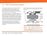
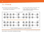
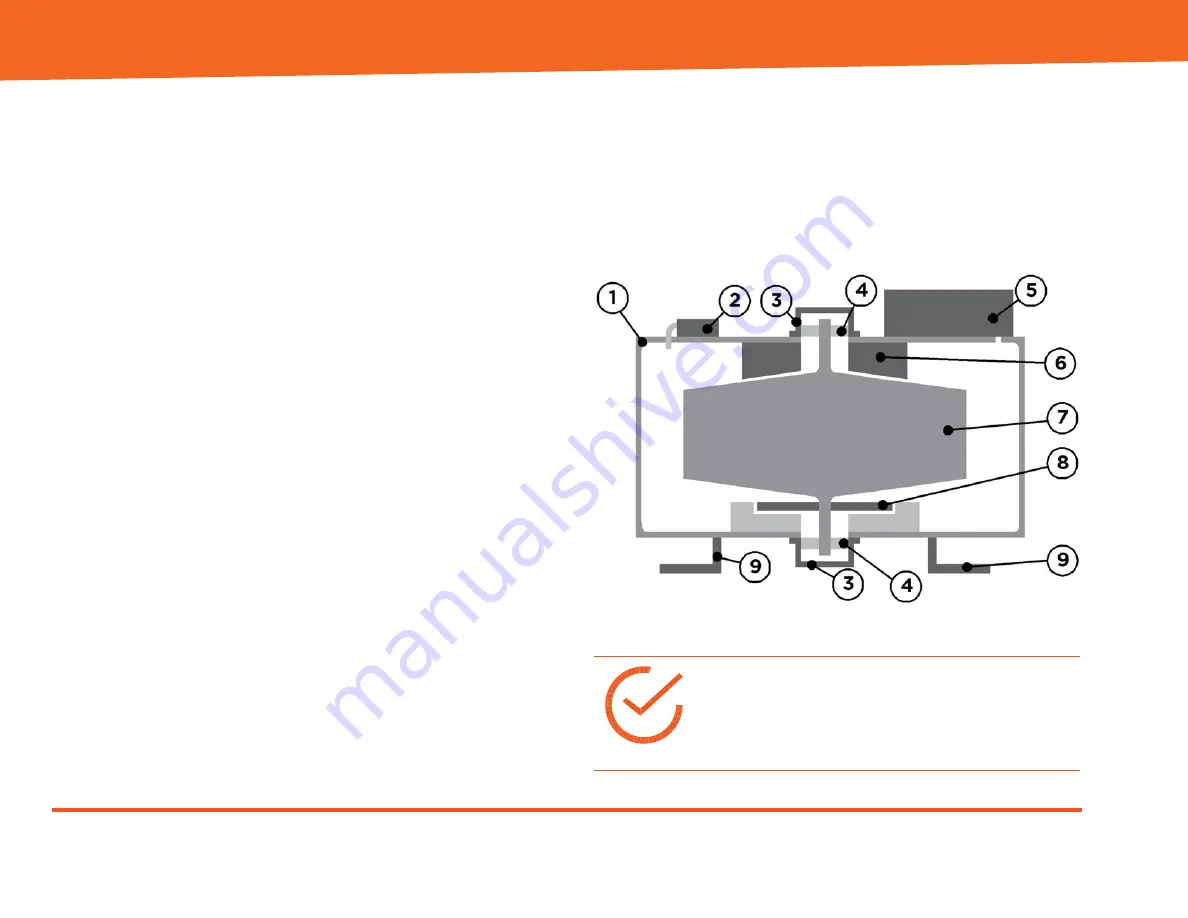
Figure 1 displays the major components that make up
the components within and attached to the Flywheel
Housing:
Figure 1: M32 flywheel components
Note: This drawing is intended for
general information only. It is not to
scale, and the actual appearance and/or
location of components may vary from
those shown.


