7
Copyright 2018 by Amber Kinetics. All rights reserved.
1 - OVERVIEW
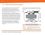
The M32 flywheel components are as follows
(numbers correspond to the callouts in Figure 1 on the
preceding image):
•
Flywheel Housing (1):
Vacuum vessel that houses
the components numbered 2 through 9.
•
Passive Vacuum Pump (2):
Canister of molecule-
adsorbing desiccants that maintain the appropriate
vacuum environment within the Flywheel Housing
(1).
•
Bearing Caps (3):
Cover and provide access to the
upper and lower Bearings (4). There is also a jack
screw underneath the lower Bearing Cap that
lowers the Flywheel Rotor (7) onto internal
supports to protect the Bearings (4) from damage
during shipping. You will remove the lower Bearing
Cap and adjust this jack screw during installation.
•
Bearings (4):
Support the Flywheel Rotor (7).
•
Electronics Enclosure (5):
Houses a number of
electronic components, including the electrical
powertrain, instrumentation, communications, and
control.
•
Offloader (6):
Electromagnet that reduces loads on
the Bearings (4) by providing a lifting force for the
Flywheel (7).
•
Flywheel Rotor (7):
Rotating mass that stores
mechanical energy for conversion into electricity.
•
Motor/Generator (8):
Converts electrical energy to
mechanical energy when the Flywheel Rotor is
charging, and vice-versa when the Flywheel Rotor
is discharging. The Motor/Generator also contains
the current-carrying conductors that route power
to and from the Electronics Enclosure (5).
•
Feet (9):
Support the Flywheel Housing (1) and
other components.
•
Capsule (not shown):
Encloses the M32 flywheel
and other components within the excavated hole.
•
Capsule Lid (not shown):
Covers the Capsule to
prevent rain and debris from falling into the
Capsule.


