background image

Copyright 2018 by Amber Kinetics. All rights reserved.

iv

M32 FLYWHEEL - INSTALLATION & MAINTENANCE MANUAL

This page intentionally left blank.

Summary of Contents for M32

Page 1: ...M32 FLYWHEEL INSTALLATION MAINTENANCE MANUAL v2 0 March 2018 ...

Page 2: ...completeness of the contents of this document and assumes no liability of any kind including the implied warranties of non infringement merchantability or fitness for particular purposes with respect to the operation or use of Amber Kinetics hardware software or other products described herein No license including implied or arising by estoppel to any intellectual property rights is granted by thi...

Page 3: ...and Benefits 4 1 3 M32 Flywheel Description 6 1 4 Theory of Operation 8 1 5 Specifications Performance 9 1 6 Safety Features 10 2 Safety 11 3 Installation 15 3 1 Planning 16 3 2 Equipment Tools 17 3 3 Site Preparation 18 3 4 Capsule Placement 19 3 5 M32 Flywheel Preparation 20 3 6 M32 Flywheel Placement 23 3 7 Electrical Connections 25 3 8 Completing the Installation 29 4 Testing and Commissioning...

Page 4: ...Copyright 2018 by Amber Kinetics All rights reserved iv M32 FLYWHEEL INSTALLATION MAINTENANCE MANUAL This page intentionally left blank ...

Page 5: ...yout and organization of this Installation Manual About Amber Kinetics Company information Features and Benefits Why the M32 flywheel compares well to batteries Description Key components of the M32 flywheel Theory of Operation How the M32 flywheel stores and discharges energy Specifications Basic mechanical and electrical specifications Safety Features How the M32 flywheel incorporates safety by ...

Page 6: ...Procedures that must be followed in a specific order appear in numbered steps 1 Perform this step first 2 Perform this step second Specific keyboard keys are depicted in square brackets and are capitalized for example ESC If more than one key should be pressed simultaneously the notation will appear as KEY1 KEY 2 for example ALT F4 Interface elements such as document titles fields windows tabs but...

Page 7: ...information that must be followed when installing commissioning operating and maintaining the M32 flywheel 3 Installation Detailed installation procedures that include site planning and preparation physical installation and the various electrical and monitoring connections 4 Testing and Commissioning Describes how to test the M32 flywheel and commission it for regular service 5 Maintenance Contain...

Page 8: ...l Monday to Friday from 8 00AM to 5 00PM Pacific time holidays excluded You may contact Amber Kinetics via the following methods 1 2 2 Features and Benefits Amber Kinetics Inc was founded in 2009 to develop and bring to market breakthrough flywheel energy storage technology Although flywheel storage is a mature technology it has been limited to short duration discharges The M32 flywheel by Amber K...

Page 9: ...cal batteries 86 round trip efficiency DC includes self discharge No daily cycling limitations No degradation over time No HVAC required Operates in hot and cold environments 40 F to 122 F 40 C to 50C Fast response time 1 second Recyclable all steel design Minimal operations and maintenance 30 year design life 10 year manufacturer warranty ...

Page 10: ...C power is inverted to variable frequency AC power that powers a Motor Generator to spin up a rotating mass which stores the electrical power as mechanical energy To discharge this process is reversed The rotor group operates in a vacuum to minimize rotational losses during storage The M32 flywheel and Capsule are installed in an excavated hole in the ground and a protective Capsule Lid is then pl...

Page 11: ...tallation Bearings 4 Support the Flywheel Rotor 7 Electronics Enclosure 5 Houses a number of electronic components including the electrical powertrain instrumentation communications and control Offloader 6 Electromagnet that reduces loads on the Bearings 4 by providing a lifting force for the Flywheel 7 Flywheel Rotor 7 Rotating mass that stores mechanical energy for conversion into electricity Mo...

Page 12: ...nergy of the Flywheel Rotor to and from electrical energy This 3 phase electric component is driven by a Pulse Width Modulation PWM voltage source inverter within the Electronics Enclosure Both the Motor Generator assembly and M32 flywheel inverter are capable of providing both positive and negative watts to the Flywheel Rotor which allows the M32 flywheel to accurately track any continuously vari...

Page 13: ...ade Seismic rating 4 USUBC Daily cycling limit none Design life 30 years Standard warranty 10 years Environmental Temperature storage 40 F to 140 F 40 C to 60 C Temperature operating 40 F to 122 F 40 C to 50 C Humidity 100 condensing Greenhouse gases zero emissions Electrical Maximum power 8 kW minimum Energy 32 kWh Full power response time 1 second Discharge duration 4 hrs minimum Efficiency roun...

Page 14: ...argins that are consistent with aerospace engineering standards Manufacturing The material used for the Flywheel Rotor is produced using a commercially proven manufacturing process that yields the cleanest highest grade steel available Testing Finished rotors are scanned for both surface and bulk defects Each rotor is then spun beyond its maximum rated operating RPM before being placed into servic...

Page 15: ...es and advice that are intended to help ensure a safe installation and operating environment These directions must be considered in addition to both standard and site specific safety best practices The order in which these guidelines appears is not intended to express or imply any priority or relative importance ...

Page 16: ...tion commissioning and operation must comply with all applicable codes and regulations for the installation site All US electrical installations must be performed by an authorized electrician in compliance with both National Electrical Code ANSI NFPA 70 and OSHA requirements in addition to all local jurisdiction requirements The M32 flywheel weighs approximately 10 500lbs 4 763kg The Capsule weigh...

Page 17: ...e sure to use safety lockout devices on all affected circuit breaker s and or power shut off s when working on the M32 flywheel or associated components to prevent accidental power on and death from electrical shock The M32 flywheel contains no user serviceable parts Under no circumstances should you open the Flywheel Housing or perform any other servicing or repair aside from that explicitly desc...

Page 18: ...Copyright 2018 by Amber Kinetics All rights reserved 14 M32 FLYWHEEL INSTALLATION MAINTENANCE MANUAL This page intentionally left blank ...

Page 19: ...ess begins with planning the installation gathering the needed equipment and tools and then preparing the site Next the M32 flywheel is installed in the ground and electrical connections are made Finally a vacuum pump is connected to the M32 flywheel s to ensure a proper level of vacuum inside the Flywheel Housing and the site wide wiring is completed ...

Page 20: ...32 flywheel installation The total DC capacity will be 8kw times the number of M32 flywheels in the installation Each block of M32 flywheels consists of two rows Figure 3 displays the minimum clearance requirements between individual M32 flywheels blocks and the site perimeter Figure 3 Clearance requirements at a multi M32 flywheel site ...

Page 21: ...g Capsule Lid Approximately 400lbs 200kg Lifting straps with shackles three required One or more tagline s and or magnetic manipulator bars for aligning and positioning the M32 flywheel and Capsule during installation Shovels and or other handheld earthmoving tools as appropriate for the installation site Socket torque wrench rated to at least 150 foot pounds 210Nm 7 213cm extension with 1 4 20 th...

Page 22: ...om the ground plus or minus 3 7cm Thus the hole must be approximately 70 178cm deep The ground surface must be leveled and smoothed to ensure proper Capsule ground clearance along the entire perimeter The bottom of the hole must be Smooth enough to provide even support across the entire base of the Capsule Level with a grade of no more than 1 Compressed to ensure that the soil can support a unifor...

Page 23: ...nto the hole If needed use one or more tagline s and or manipulator s to align and center the Capsule inside the hole 4 Backfill the gap between the Capsule and sides of the hole being sure to compact the soil as much as possible see Figure 5 During backfilling Keep the floor level with a grade of 1 or less Leave room to allow electrical conduit installation Be careful to avoid spilling dirt or de...

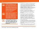
Page 24: ...procedure described in this section To adjust the jack screw 1 Install the vacuum vent tool on the KF40 flange and then open the vacuum valve Figure 6 KT40 flange and vacuum valve 2 Connect the Handheld Load Cell Reader to the DB9 connector on the upper Bearing Cap see Figure 7 and then power it on It should read 0lbs Figure 7 DB9 connector on upper Bearing Cap WARNING ENSURE THAT THE M32 FLYWHEEL...

Page 25: ...her storage 5 Loosen the locknut A securing the jack screw B to the M32 flywheel using the 1 5 39mm open ended wrench Figure 9 Locknut A and jack screw B 6 Using the socket torque wrench with a 1 5 39mm socket turn the jack screw B clockwise until the Handheld Load Cell Reader indicates 125lbs 10lbs 7 Turn the jack screw B counterclockwise 220 degrees 10 degrees 8 Record the load displayed on the ...

Page 26: ...oving the O ring seal 12 Inspect the O ring seal to ensure that it is intact replace if damaged or broken 13 Clean the O ring seal and the surface of the Bearing Cap using lint free wipes and denatured alcohol and then replace the O ring seal in the groove 14 Lift the lower Bearing Cap into position against the Flywheel Housing being sure that the bolt holes are aligned 15 Insert and hand tighten ...

Page 27: ...ure 12 M32 flywheel and Capsule with lift points 2 Slowly lower the M32 flywheel into the Capsule using the tagline s and or magnetic manipulator s to align it such that the three feet are centered over the three bolts at the bottom of the Capsule The feet must not touch the bolts See Figure 13 Figure 13 The feet must be properly aligned 3 Disconnect the hoist CAUTION MOVE THE M32 FLYWHEEL SLOWLY ...

Page 28: ...cuum valve remove the vacuum relief tool and then connect a vacuum pump to the KT40 flange Start the pump and then open the valve conduit not shown for clarity Figure 15 KT40 flange and vacuum valve 6 Follow the instructions provided with your vacuum system to complete the vacuum pump down and the installation of any additional vacuum accessories Note Your vacuum valve configuration on your M32 fl...

Page 29: ...ck copper wire size 14 8AWG and one bare grounding copper wire size 14 4AWG Connect a 3 4 flex conduit to the middle port of the Electronics Enclosure This conduit will contain one white one black and one green copper wire size 22 12AWG Connect a 1 1 4 flex conduit to the top port of the Electronics Enclosure This conduit will contain two Cat6a Ethernet cables Figure 16 Flex conduits connected to ...

Page 30: ... pins and latches on Electronics Enclosure 3 Remove the fasteners and then lift the upper electronics tray up to gain access to connect the DC wires to the terminals on the lower electronics tray 4 Connect the DC wires as follows Red wire to the positive terminal Black wire to the negative terminal Bare wire to the grounding lug on the Electronics Enclosure Figure 18 DC connections lower tray 5 Lo...

Page 31: ...d G terminal Bare or green wire from the ground G terminal to the grounding lug on the Electronics Enclosure Figure 19 AC connections upper tray 7 Connect the flywheel debug Cat6a Ethernet cable to the Ethernet to USB adapter unit may vary from that shown in Figure 21 Use the provided cable tie points to provide strain relief for the cable cable ties not shown Figure 20 Debug Cat6a Ethernet connec...

Page 32: ...vided cable tie points to provide strain relief for the cable cable ties not shown Figure 21 Communications Cat6a Ethernet connection 9 Connect the M32 flywheel s to the following components and complete all external connections to those components Grid tie inverter DC Balance Load if needed Industrial PC Ethernet switch router Figure 22 depicts the wiring diagram for a generic site your specific ...

Page 33: ... fall inside the Capsule s 3 Connect a lifting strap and shackle to the lifting point at the top of the Capsule Lid Connect the other end of the strap to the crane or forklift and then hoist the Capsule Lid up and over the protruding Capsule If needed use one or more tagline s and or manipulator s to center the Capsule Lid as you gently lower it into position being sure not to damage any conduits ...

Page 34: ...Copyright 2018 by Amber Kinetics All rights reserved 30 M32 FLYWHEEL INSTALLATION MAINTENANCE MANUAL This page intentionally left blank ...

Page 35: ...Copyright 2018 by Amber Kinetics All rights reserved 31 4 Testing and Commissioning This chapter describes the pre commissioning and spin up procedures for the M32 flywheel ...

Page 36: ...on of the installed M32 flywheel s paying particular attention to the following Each M32 flywheel is properly secured to its Capsule All electrical and communications connections to the M32 flywheel s have been completed in accordance with the instructions in this manual There is no debris in the Capsule s Station power and network communications are available to the M32 flywheel s WARNING DO NOT ...

Page 37: ...nfiguration data b Acquire IP address c Confirm debug programming 3 Verify hardware settings and state a Offloader b Field windings c Vacuum 4 Energize DC 5 Startup a Open Loop 0 0 7 Hz b Spin up 0 7 10 Hz c DC Regulation 10 Hz 6 Resonance Traversal 24 40 Hz 7 Charge to Min SOC 50 Hz 8 Charge to Max SOC 150 Hz a Perform coasting loss test b Charging pauses at 0 25 50 75 and 100 SOC to measure coas...

Page 38: ...Copyright 2018 by Amber Kinetics All rights reserved 34 M32 FLYWHEEL INSTALLATION MAINTENANCE MANUAL This page intentionally left blank ...

Page 39: ...Copyright 2018 by Amber Kinetics All rights reserved 35 5 Maintenance This chapter describes the regular maintenance required to keep the M32 flywheel in optimal operating condition ...

Page 40: ... Time Procedure At least once per quarter every 90 days Inspect the perimeter of the M32 flywheel cover for weeds trash and or other debris that might be blocking the ventilation inlet and remove if present Every 10 years after initial installation Contact a certified Amber Kinetics service provider to replace the upper and lower Bearings and service the vacuum system ...

Page 41: ...37 Copyright 2018 by Amber Kinetics All rights reserved 5 MAINTENANCE This page intentionally left blank ...

Page 42: ...M32 FLYWHEEL INSTALLATION MAINTENANCE MANUAL v2 0 March 2018 2018 Amber Kinetcs Inc All rights reserved ...

Reviews: