Copyright 2018 by Amber Kinetics. All rights reserved.
8
M32 FLYWHEEL - INSTALLATION & MAINTENANCE MANUAL
1.4 - Theory of Operation
The M32 flywheel stores kinetic energy in a massive
rotating disk. The amount of energy stored is defined
by the equation
E=½
J
ω
2
, where:
•
J is the moment of inertia (related to the mass and
size of the disk)
•
ω
is the rotational speed.
The rotational speed of the M32 flywheel accurately
characterizes the state of charge of the system, and
this speed will vary slowly between its minimum and
maximum limits over the course of a 4-hour charge or
discharge period. Unlike batteries, the M32 flywheel
exhibits no capacity fade over time.
As described in
“M32 Flywheel Description” on page 6
the Motor/Generator assembly within the M32
flywheel converts the kinetic energy of the Flywheel
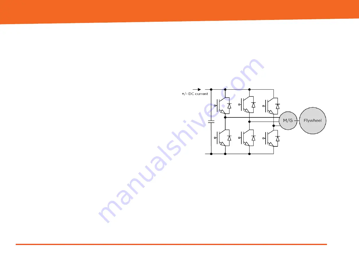
Rotor to and from electrical energy. This 3-phase
electric component is driven by a Pulse Width
Modulation (PWM) voltage-source inverter within the
Electronics Enclosure. Both the Motor/Generator
assembly and M32 flywheel inverter are capable of
providing both positive and negative watts to the
Flywheel Rotor, which allows the M32 flywheel to
accurately track any continuously variable charge/
discharge profile that falls within its maximum power
and energy ratings.
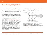
Multiple M32 flywheels can be connected in parallel to
meet desired power and energy requirements. The
inverter in each M32 flywheel connects to a common
DC bus, as shown in Figure 2.
Figure 2: DC bus connection
A third-party grid-tie inverter (not shown) interfaces
between the DC bus and the AC line. A single central
grid-tie inverter can serve many parallel M32
flywheels. Please contact Amber Kinetics as described
in
tie inverter requirements.


