Analysis and reporting
User manual
Page 40 of 68
© Amberg Technologies, 2018
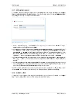
Figure 25. New analysis wizard
1. On the first wizard page, set
Layer thickness
as analysis type. Enter a name for the analysis,
optionally add a comment and click
Next
.
2. On the second wizard page, select a
Reference construction stage
that will be used for all
axis-related calculations displayed in the diagrams. Optionally select
Additional construc-
tion stages for display
, whose design data will be used for graphical purposes only. Set
Deviation unit and format
and
Stationing mode
that you want to use in this analysis. If
necessary, you can change all these settings in the settings dialog later. Click
Next
.
3. On the third wizard page, you must select two different construction stages as data source.
Point clouds from the
Original construction stage
are used to compare the point clouds
from the
Comparison construction stage
against.
After the wizard has been completed, a new analysis node is created in the
Project tree
under
the
Analysis
node of the current heading. The analysis editor opens automatically.
4.2.2 Analysis editor
To open an existing point cloud analysis, double-click on the according node in the Project tree.
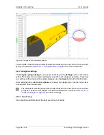
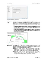
The analysis editor consists of the elements described below.
Summary of Contents for Tunnel 2.0 - Tunnelscan
Page 2: ......
Page 6: ...Page 6 of 68 ...
Page 10: ...Page 10 of 68 ...
Page 12: ...Page 12 of 68 ...
Page 26: ...Page 26 of 68 ...
Page 62: ...Page 62 of 68 ...
Page 66: ...Page 66 of 68 ...
Page 67: ......


