background image

Microphone ABT-M04N 

User Manual

8

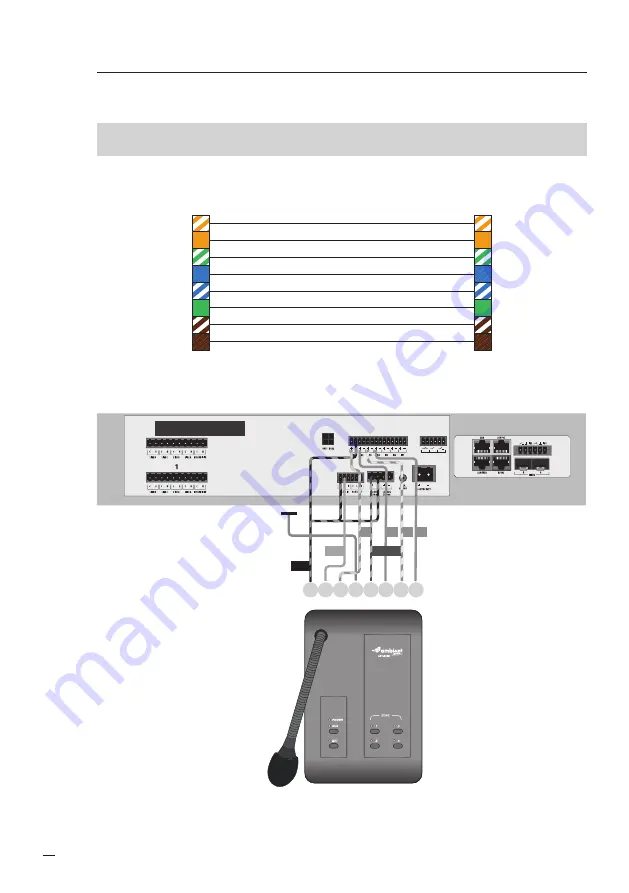
3.  Connection diagram

Fig. 2. 

568B

wiring standard

568B

wiring standard

GND

OUT

Z1

Z2
Z3
Z4

Do not use - MICOM

POWER 24/48 VDC +

2
3

4
5

6
7
8

1
2
3
4
5
6
7
8

1

Microphone Connector pinout

Fig. 3. 

OUT3

OUT2

OUT1

1 2 3 4

6 7 8

5

GND

OUT

POWER

Z4

Z3

Z2

miniVES 4001LN

Z1

Connecting the ABT-M04N microphone to miniVES and midiVES

Summary of Contents for ABT-M04N

Page 1: ...User Manual EN Microphone ABT M04N www ambientsystem eu ver 04 2022 ...

Page 2: ...icates a potentially hazardous situation If not avoided this could result in property damage or risk of damage to the unit Table of Contents 1 Safety___________________________________________________________________________________ 2 2 ABT M04N______________________________________________________________________________ 6 3 Connection diagram______________________________________________________...

Page 3: ...ons have been adhered to 8 Do not install near any heat sources such as radiators heat registers stoves or other apparatus including amplifiers that produce heat or in direct sunlight 9 No naked flame sources such as lighted candles should be placed on the apparatus 10 Do not defeat the safety purpose of the polarized or ground type plug A polarized plug has two blades with one wider than the othe...

Page 4: ... For apparatus with audio output to prevent possible hearing damage do not listen at high volume levels for long periods 22 Do not disassemble the device or attempt to repair or modify it The device does not include user replaceable components inside the chassis Opening the chassis and unauthorized repairs will void the warranty Unauthorized substitutions may result in fire electric shock or other...

Page 5: ...stallation rules For pluggable equipment the socket outlet shall be installed near the equipment and shall be easily accessible This label may appear on the bottom of the apparatus due to space limitations Caution To reduce the risk of electrical shock DO NOT open covers Refer servicing to qualified service personnel only Warning To prevent fire or shock hazard do not expose units to rain or moist...

Page 6: ...ect the Zones by pressing designated buttons and then press MIC button The Mic LED will start blinking green for the time of matrix activation When Mic led is green and red ring on the goose neck lights up microphone is ready for live announcement On the other microphones connected in the chain AUX LED and MIC LED are blinking indicating that live announcement is being broadcast on other microphon...

Page 7: ...n indicates AUX activated on the other microphone 3 MIC activation Blinking green indicates wait for activation or busy Green indicates ready for live announcement 4 Zone selector green light indicates selected zones 5 RJ 45 IN and OUT for daisy chain connection 6 3 5 mm stereo jack for AUX 7 AUX volume knob 8 Microphone volume knob 1 2 3 4 5 6 7 8 ...

Page 8: ...andard 568B wiring standard GND OUT Z1 Z2 Z3 Z4 Do not use MICOM POWER 24 48 VDC 2 3 4 5 6 7 8 1 2 3 4 5 6 7 8 1 Microphone Connector pinout Fig 3 OUT3 OUT2 OUT1 1 2 3 4 6 7 8 5 GND OUT POWER Z4 Z3 Z2 miniVES 4001LN Z1 Connecting the ABT M04N microphone to miniVES and midiVES ...

Page 9: ...4N for 24V 600 1 465 2 380 3 320 4 276 5 243 6 217 7 197 8 180 9 164 10 153 11 142 12 133 13 125 14 117 15 Total cable length in meters Number of M04N for 48V 2200 1 1700 2 1387 3 1170 4 1012 5 892 6 800 7 720 8 660 9 604 10 560 11 520 12 487 13 ...

Page 10: ... 23 283 24 274 25 264 26 255 27 247 28 238 29 231 30 225 31 217 32 211 33 205 34 200 35 c typical Cat5e cable 4 miniVES and midiVES settings Change the generic name of the Audio input no 3 to Local Audio IN In the matrix configuration tab create Matrix1 Audio input Local Audio IN Selected zones Zone 1 ...

Page 11: ...ng Matrix2 Mode stop Input 3 Active Start Stop matricing Matrix3 Mode start Inactive Start Stop matricing Matrix3 Mode stop Input 4 Active Start Stop matricing Matrix4 Mode start Inactive Start Stop matricing Matrix4 Mode stop 5 Technical data Model ABT M04N Operating voltage 20 57 VDC Nominal current 74mA for 24VDC IDLE current 22mA for 24VDC Efficiency 10 mV Pa Microphone socket GX12 3 pin Outpu...

Page 12: ...www ambientsystem eu Ambient System Sp z o o ul Bysewska 27 80 298 Gdańsk Poland T 48 58 345 51 95 ambient ambientsystem eu ...

Reviews: