
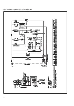


Figure 10 Damper settings
5 Commissioning
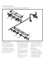
Inspect installation and ensure it has been
carried out in accordance with these
instructions.
Ensure that electrical and gas supplies are
isolated.
The gas supply should be purged and
tested for soundness in accordance with the
British Standard BS 6891:1998,
BS 7671:1992, IGE/UP/2 and any other
British Standards and Codes of Practice.
Ensure that the settings of any time switch
and thermostat are such that the heating
system will be required to operate (or put
the mode switch to ‘constant’).
Before attempting to start up the heating
system it is essential to perform the
preliminary balancing of the vacuum level at
each burner unit.
Isolate each heater unit by unplugging each
electrical connector and closing each gas
isolating valve.
Heater type
Damper setting when hot (mbar)
Heater type
Damper setting when hot (mbar)
AR
13
SHN/
22
1.7
ARE
13
SHN/
22
1.1
AR
13
SHP/
22
1.7
ARE
13
SHP/
22
1.1
AR
22
SHN/
27
1.4
ARE
22
SHN/
27
1.1
AR
22
SHP/
27
1.4
ARE
22
SHP/
27
1.1
AR
22
SHN/
32
1.4
ARE
22
SHN/
32
1.1
AR
22
SHP/
32
1.4
ARE
22
SHP/
32
1.1
AR
22
SHN/
36
1.4
ARE
22
SHN/
36
1.1
AR
22
SHP/
36
1.4
ARE
22
SHP/
36
1.1
AR
22
SHN/
39
1.4
ARE
22
SHN/
39
1.1
AR
22
SHP/
39
1.4
ARE
22
SHP/
39
1.1
AR
35
SHN/
33
1.5
ARE
35
SHN/
33
1.2
AR
35
SHP/
33
1.5
ARE
35
SHP/
33
1.2
AR
35
SHN/
42
1.2
ARE
35
SHN/
42
1.0
AR
35
SHP/
42
1.7
ARE
35
SHP/
42
1.0
AR
35
SHN/
51
1.0
ARE
35
SHN/
51
1.0
AR
35
SHP/
51
1.5
ARE
35
SHP/
51
1.0
AR
40
SHN/
42
1.6
ARE
40
SHN/
42
1.4
AR
40
SHP/
42
1.4
ARE
40
SHP/
42
1.4
AR
45
SHN/
50
1.9
ARE
45
SHN/
50
1.6
AR
45
SHP/
50
2.0
ARE
45
SHP/
50
1.6
AR
45
SHN/
60
2.0
ARE
45
SHN
/60
1.9
AR
45
SHP/
60
2.3
ARE
45
SHP/
60
1.6
AR
50
SHN/
50
1.9
ARE
50
SHN/
50
1.8
AR
50
SHP/
50
2.0
ARE50SHP/50
2.3
AR
50
SHN/
60
2.0
ARE
50
SHN/
60
1.8
AR
50
SHP/
60
2.3
ARE50SHP/60
2.3
N & P refer to natural gas or propane respectively.
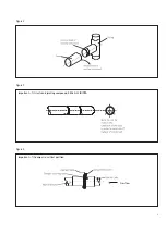
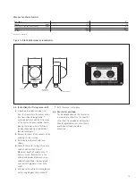
Adjust the damper at exit of each heater
using a 4mm hexagon wrench in the M8
locking screw. Observing the vacuum
reading using a ‘U’ tube manometer
connected to the vacuum test point (see
figure 4) set each damper in turn to give a
hot conditions reading as below.
Referring to each unit
Open isolating valve and test gas
connections for soundness using leak
detecting solution. Remove the combustion
chamber cover plate by unscrewing the
fixing screws. Take care not to damage the
sealing gasket. Inspect the burner and
electrode assemblies ensuring these are
securely fixed and all electrical connections
securely made. Replace the cover plate
ensuring that the sealing gasket is correctly
positioned and the screws are fully
tightened. The heater will not operate until
this plate is refitted.
Remove the safety control housing cover
plate by unscrewing the securing screws
and folding down/lifting off the plate.
Ensure all internal components are securely
fixed and all connections securely made.
Reinsert the electrical connector to the
burner control assembly.
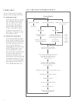
To allow the heater to start up it is
necessary to switch off the whole system
at the time switch or manual switch and
allow the fan to stop completely before
switching on again. At this point the
individual heater unit will start up with
the following sequence.
The red
mains on
lamp will illuminate and
the main fan will start to run. Safe-start
checks are carried out automatically. After
the fan has run up to full speed and a
satisfactory vacuum condition has been
established at the burner, a purge period of
approximately 9 seconds will commence.
At the end of the purge period the ignition
sequence will commence. The spark ignition
will be energised producing a spark at the
ignition electrode. The gas solenoid valve
is energised and will open.
9


