background image

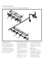
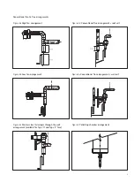
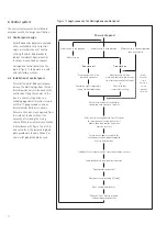
4 Fan to flue arrangement

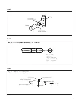
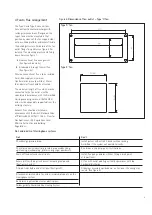
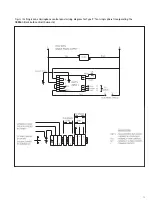
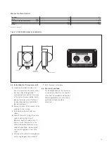
Figure 6 Dimensions of fan outlet – Type ‘0’ fan

Type ‘0’ fan

Type ‘2’ fan

Do’s

Don’t

Check design pressure drop.

Install system with extra 90º bends without asking
Ambi-Rad if the system will operate correctly.

Check for corrosive industrial process in proposed building – 

Run drains in copper pipe as it will corrode.

eg. cleaning, electroplating, printers using sugar powder etc.

Drain all flue ducts and seal all joints.

Install flue going upwards without fitting a drain point 
at lowest level. 

Secure joints with pop rivets as well as sealing compound.

Fit fan with outlet pointing vertically upwards or with top

(See figures 2 and 3)

horizontal discharge.

Fit drain traps before and after fans. (See figure 8)

Fit damper assembly upside down, on its side or the wrong way 
round.  (See figure 4)

Fit expansion joints before fan and at intermediate points on the
Herringbone system. 

Run drains in galvanised steel or plastic pipes.

Follow guide to Combined Flue Heating System.

Do’s and don’ts of Herringbone systems

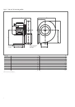
The Type ‘0’ and Type ‘2’ vacuum fans 
have bottom horizontal discharge with
rectangular connections (flanged on the
type 0) and must be mounted in that
position by means of the fan support stool
onto a suitable platform or brackets fixed to
the building structure. For details of the fan
outlet flange fixing holes see figure 6. For
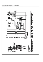
details of fan mounting bracket and fixing
down holes see figure 7.

a

A conventional flue arrangement. 
(See figures 8d and 8e)

b

A telescopic through the wall flue. 
(See figure 8c)

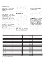
Where a conventional flue is to be installed,
Ambi-Rad supply an aluminium
transformation piece to which a150mm
(6in) diameter flue should be attached. 

The maximum length of flue which may be
connected to the fan outlet must be
calculated in accordance with the Ambi-Rad
Herringbone design manual (Ref 042/93)
and must be adequately supported from the
building structure.

Exhaust flues should be installed in
accordance with the British Standard Code
of Practice BS 5440: Part 1:1990 – Flues for
Gas Appliances, I.E.E. Regulations, Local
Ministry Authorities and Building
Regulations.

6

Summary of Contents for Herringbone HB

Page 1: ...HERRINGBONE HB COMBINED FLUE SYSTEM...

Page 2: ...Index General arrangement of Ambi Rad Herringbone system Instructions and installation Manifold assembly Fan to flue arrangement Commissioning Control system Service instructions 7 6 5 4 3 2 1 1...

Page 3: ...arrangement The exhaust flue should be adequately supported from the building structure and installed in accordance with the British Standard Code of Practice Flues for Gas Appliances Local and Minis...

Page 4: ...ters in the desired position the manifold system should be laid out on the floor where possible to the design layout before erecting After allowing for a minimum of 75mm 3in of penetration of the fitt...

Page 5: ...Figure 2 Figure 3 Figure 4 Important fit damper in vertical position Gas flow Important fit rivets and jointing compound SEAL ALL JOINTS 4...

Page 6: ...AR installation manual GB ARE E 079 0501 Figure 5 3 4 Condensate trap A condensate trap assembly must be provided at the end of the manifold system before the hot gas vacuum fan See figure 8a The min...

Page 7: ...o Combined Flue Heating System Do s and don ts of Herringbone systems The Type 0 and Type 2 vacuum fans have bottom horizontal discharge with rectangular connections flanged on the type 0 and must be...

Page 8: ...Figure 7 Vacuum fan mounting details Fan type 0 2 A 124 80 B 38 35 C 175 174 D 7 1 7 E 209 125 F 153 100 G 42 25 H 239 120 J 340 210 K 332 205 L 363 215 All dimensions are in millimetres see Fig 6 7...

Page 9: ...ure 8b Low fan arrangement Figure 8d Conventional flue arrangement roof exit Figure 8e Conventional flue arrangement wall exit Figure 8c Stainless steel telescopic through the wall arrangement availab...

Page 10: ...0 2 3 N P refer to natural gas or propane respectively Adjust the damper at exit of each heater using a 4mm hexagon wrench in the M8 locking screw Observing the vacuum reading using a U tube manometer...

Page 11: ...ssure or anti clockwise to decrease the pressure Set the burner pressure to the required figure given on the data label Switch off the heater by pulling out the mains connector Disconnect U tube manom...

Page 12: ...cordance with figure 12a or 12b and cut holes in the removable gland plate provided in the box Conduit or strain relief glands should be used Power onto panel Mode switch in off position Mode switch i...

Page 13: ...Figure 12a Single zone Herringbone control panel wiring diagram for Type 2 fan single phase incorporating the ARBB65 black bulb control thermostat 12...

Page 14: ...Figure 12b Wiring diagram for Type 0 fan single phase 13...

Page 15: ...r unit by undoing the four screws c Fix the base to the wall with two screws d Connect the sensor using a three core cable of not less than 0 5mm2 Maximum length of cable is 200m if 0 5mm2 is used Sec...

Page 16: ...4 489700 Facsimile 01384 489707 UK sales email sales ambirad co uk Website www ambirad co uk 7 Service instructions Under normal working conditions it is recommended that the Ambi Rad heater has a rou...

Reviews: