0501UCA
10/25
8. COMMISSIONING, LIGHTING & OPERATION
COMMISSIONING
8.1 Normally UCA air heaters do not require
commissioning. Final testing after production
ensures that:
If installation has been carried
out strictly in accordance with this
document
, the appliance is ready to be taken
into service.
8.2
Checks to ensure;
-
earth continuity
-
resistance to earth
-
phase supply to correct terminals
-
current rating and fuse value
-
correct supply gas pressure
-
correct burner gas pressure
-
satisfactory & smooth ignition
-
flue system is venting the products of
combustion to outdoor atmosphere, must
be made.
8.3
In addition to the above requirements checks
to ensure that the fan/s rotate freely and in
the correct direction and the fan guards are
fitted correctly and securely.
8.4
Euroventer:
Installations may include an Euroventer. This
device is an electrically powered fan fitted into
the flue system. Its inclusion will be obvious.
When a Euroventer is fitted the control
switching of the air heater as described in 8.9
is via the Euroventer, which is operationally
proven prior to the burner control being
activated.
8.5
LIGHTING THERMOELECTRIC
Models UCA 25
→
45
-
Ensure that the air discharge louvres are
set to an open position;
- Turn
ON
the gas supply to the air heater;
- Switch
ON
the electricity supply to the air
heater;
-
Set room thermostat or remote control to
an
OFF
setting;
-
If fitted ensure that a time control is at an
ON
setting;
-
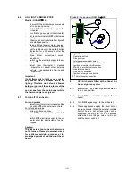
Observe gas control details from figures
8 set control to star position:
Using a lighted taper or match depress
and hold the control valve start knob and
apply light to the ignition burner. When
the ignition burner has lit, hold control for
30 seconds. Ignition burner should
remain alight when released. Turn knob
to
"Flame"
position.
Note:
-
If ignition burner has not lit wait five minutes
and repeat the lighting procedure
- Having
established
the ignition burner set
control to
"Flame"
position, appliance operation
is now fully automatic;
-
Set room thermostat to call for heat and/or
adjust to the desired comfort level. The pilot
burner will now light the main burner.
-
In the event that the pilot flame goes out for any
reason it is important to wait five minutes before
attempting to relight the gas due to the
possibility of main gas flowing from the main
burner if the thermocouple has been energised.
-
To stop the burner, put the control knob to the
OFF
position as indicated. It must be noted
there is a security interlock which prevents
relighting for one minute.
Figure 8 : Gas control type TYPE UCA 25
→
45
Legend
1 Control
knob
2 Governor
3
Inlet gas pressure test point
4
Burner pressure test point
5
Pilot gas throttle screw
6
Main burner electrical connection
7 Gas
inlet
8 Gas
outlet
9
Pilot gas line connection
10 Thermocouple
connection


