0501UCA
11/25
8.6 LIGHTING
THERMOELECTRIC
Models: UCA 55
→
95
-
Ensure that the air discharge louvres are
set to an open position;
- Switch
OFF
the electricity supply to the
air heater;
- Turn
ON
the gas supply to the air heater;
-
Set room thermostat to
OFF
or its lowest
setting;
-
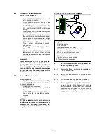
Observe gas control details from figure 9
note start gas position;
-
Using a lighted taper or match, depress
the control valve start button and apply
light to ignition burner. Keep start button
depressed for ± 20 seconds after the
ignition burner has lit;
- Close burner compartment access
panel/ door;
- Switch
ON
the electricity supply to the air
heater;
- adjust room thermostat to desired
temperature or adjust other external
controls to requirements of timing and
temperature.
Important:
If pilot flame fails to light or goes out for
any reason allow 3 minutes before re-
lighting. This time must also be allowed
before re-ignition if there is a failure of the
main burner for any reason because gas
can escape from the main burner whilst
the thermocouple is energised.
8.7
To turn off the air heater;
For short periods
-
Adjust room thermostat to lowest setting
or switch
OFF
other external controls;
For extended periods
-
Follow a) above and then;
- Turn
OFF
gas control valve figures 8 &
9;
- Switch
OFF
electricity supply to the air
heater after the air circulation fan has
stopped.
Caution:
The gas service tap to the air heater must
not be turned off except in emergencies or
for appliance servicing purposes or for
prolonged periods of shut down of the air
heater
.
Figure 9 : Gas control UCA 55
→
95
8.8
UCA Air heaters fitted with optional Hot
Surface Ignition system.
8.8.1
Ensure that the air discharge louvres are set
to an open position;
8.8.2 Switch
ON
the electricity supply to the air
heater;
8.8.3 Turn
ON
the gas supply to the air heater;
8.8.4
These appliances employ the direct burner
ignition principle. When the external controls
call for heat, a hot surface igniter will be
energised and will glow for ± 15 seconds,
after which time the gas valve(s) will open
and the burner will be lit.
Legend
1. Operating button
2. Gas governor
3. Inlet gas pressure test point
4. Outlet/burner gas pressure test point
5. Ignition burner gas throttle screw
6. Main burner electrical connection
7. Gas inlet connection
8. Gas outlet connection
9. Ignition burner gas connection
10. Thermocouple connection


