0501UCA
15/25
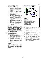
Figure 13.
THERMOELECTRIC IGNITION BURNER DETAILS
Figure 14.
HOT SURFACE IGNITER ASSEMBLY DETAILS
9.14 Figure 13 shows the approximate flame pattern
of the ignition burner and its relationship to the
flame proving thermocouple.
NOTE: Location of the spacer rings when
replacing a thermocouple. Ensure that pilot
flame plays on thermocouple hot-tip only, i.e.
top of thermocouple.
9.15 After any service work has been carried out
re-commission the air heater following the steps
outlined in clauses 8.2 and 8.3 of this
document.


