0501UCA
17/25
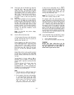
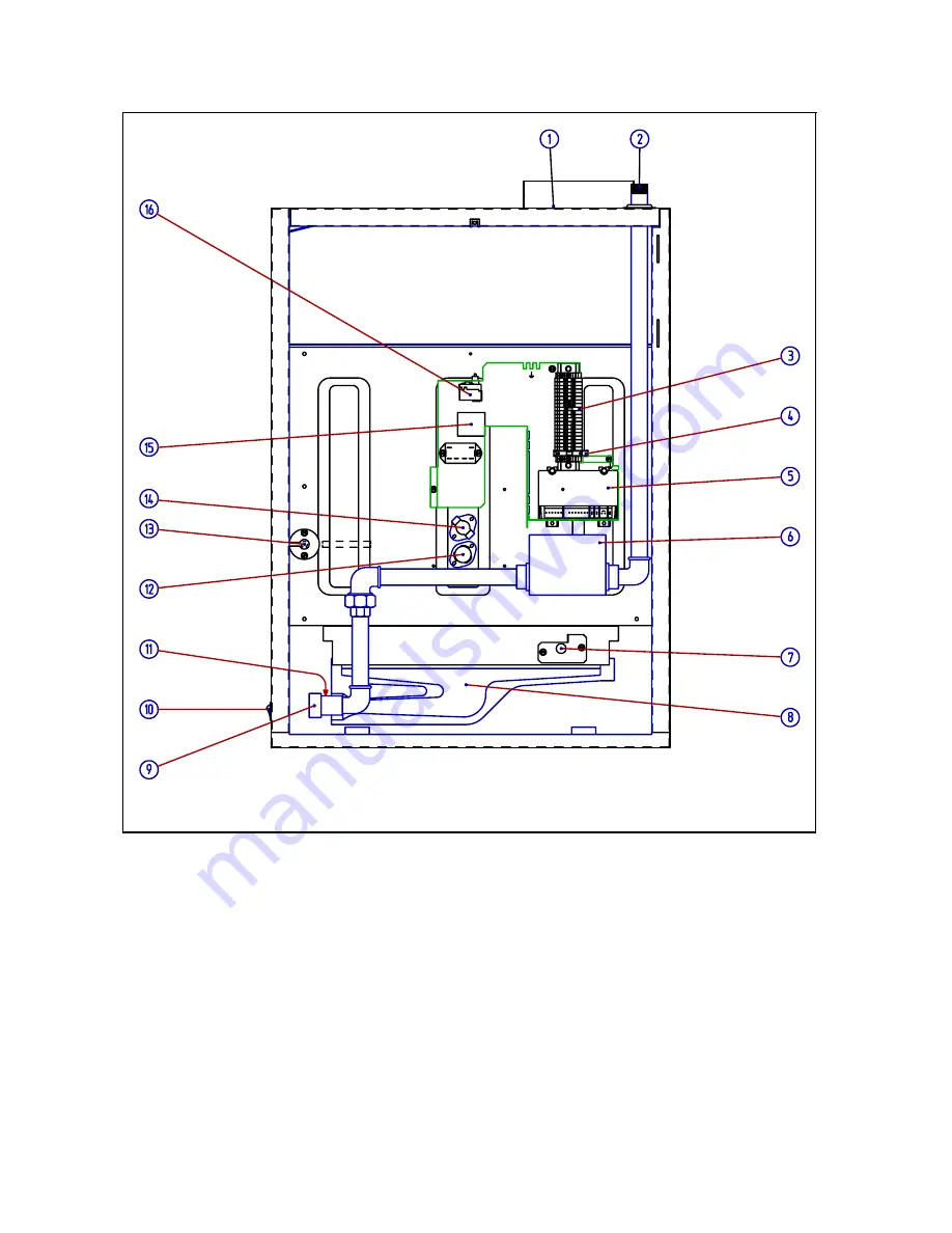
Figure 16 : COMPONENT PARTS LOCATION HOT SURFACE IGNITION BURNER CONTROLS
Legend figure 15
1. Flue
socket
2. Gas
inlet
connection
3. Main
wiring
terminals
4. Controls
fuse
5.
Automatic electronic burner control
6. Gas
valve
7. Hot
surface
ignition
8. Burner
ribbon
9. Burner
manifold
10. Burner
fail
indicator
11.
Burner gas pressure test point
12. Thermal
fan
control
13.
Thermal overheat control LC3 capillary
14.
Thermal over heat (limit) control LC1 & LC2 on
models 75 & 95
15.
Not applicable for GB & IE
16.
Thermal overheat control LC3


