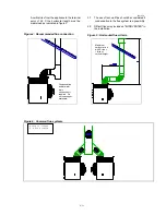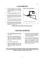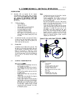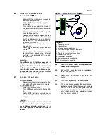
0501UCA
22/25
14. USER INSTRUCTIONS
NOTE:
Keep a copy of this document near your air heater !
WARNING: This appliance must be earthed.
14.1 Your UCA air heater should have been
installed, commissioned and tested in
accordance with these the manufacturer's
written recommendations.
14.2 In the interest of safety and user satisfaction it
is important that this document is read and
understood. If in any doubt, consult your
installer or your local gas region supplier.
14.3 It is in your interest to ensure proper service
and maintenance is carried out on a regular
basis by a competent service undertaking.
AmbiRad suggests at least once every year.
14.4 In the event of difficulties in resolving any of
these matters, please do not hesitate to contact
the manufacturer or their official distributor.
14.5 About your air heater
:
- UCA air heaters are state of the art gas fired
appliances and incorporate an atmospheric
burner which uses air for combustion taken
from the location in which the air heater is
installed. Products of combustion are vented
to outdoor atmosphere via a permanently
connected natural draught flue. The flue
system may incorporate a fan to assist
evacuation of the flue gasses.
- These heaters have not been designed for
use with air distribution ducting. Through the
wall straight stub ducts are allowed up to a
maximum of 1.0 m long.
- The location of the air heater should be
maintained at normal ambient pressure.
Changes to the building after air heater
installation should have regard to the heating
installation, i.e. creation of draughts from
doors, windows. Other air handlers and
installation of air extraction equipment may
cause equipment may cause negative
pressure environments, which can, seriously
affect the operation of this type of air heater.
- The space heating process using UCA air
heaters is for air to be circulated through the
appliance whereby it gains heat from a heat
exchanger which is directly discharged into
the space to be heated.
The air is eventually re-circulated through the
appliance thus an unobstructed path for the
return air must be maintained. This is
particularly important when installed to blow
through the wall between two rooms.
14.6
How the air heater works :
Gas is burned by an atmospheric burner which
fires into a multiplex combined
combustion/heat exchanger. The gas burner
is controlled by a gas valve which is switched
via external controls i.e. a room thermostat and
time switch.
UCA air heaters are available with a choice of
burner ignition systems;
Thermoelectric: Incorporate a permanent pilot
flame on a separate ignition burner which
requires manual lighting as described below,
or;
Automatic Hot Surface Ignition System: Which
operates fully automatically at the dictates of
the external time and temperature controls.
Air heaters with a permanent flame ignition are
protected by a thermo-electric flame failure
device. Once the ignition burner has been lit
and established the heater operation is
automatic following the dictates of the external
timing and/or temperature controls.
Air heaters with hot surface ignition are
protected against flame failure by the igniter
acting as a sensor in the burner flame. When
the external controls signal a call for heat the
igniter becomes energised and after a short
time it glows, when sufficient heat to light the
gas has been generated, then the gas valve/s
open and the burner lights.
Safety against overheating is assured by the
inclusion in the controls circuit of two thermal
overheat controls. There is an automatic
recycle control which protects against low air
flows i.e. clogged air ways, fan failure ! The
second control being a super overheat control
which operates to switch off the ignition burner
in the event of gross overheating for any
reason. Two types of this control are
employed for this function to suit availability,
they can be identified by looking into the
controls compartment of the air heater and
comparing with figures 15 or 16. Manual
intervention to relight the ignition burner is
necessary for thermoelectric appliances,

