0501UCA
24/25
To turn off the air heater for short periods
a Adjust room thermostat to lowest setting or
switch to off other external controls; To
turn off for prolonged periods, carry
out 'a' above then;
b Turn off gas control valve fig 19 or 20;b
c Switch off main electricity supply after air
circulation fan has stopped;
To turn off for prolonged periods, follow
procedure outlined above & then turn off the
gas inlet service tap.
To light the air heater:
Hot surface ignition systems;
1. Turn on the gas supply to the air heater;
2. Switch on the electricity supply to the air
heater;
3. Ensure that time switch (if fitted) is set to
an
ON
cycle;
4. Adjust room comfort control/ thermostat to
desired temperature;
5. Air heater will now light automatically when
the room thermostat calls for heat.
6. If
the
appliance does not light:
a) check the automatic burner control does not
require resetting. An indicator light will glow
on the front panel of the appliance or on a
remote control where applicable. Reset by
press the light button on the appliance or
remote control.
b) check if the thermal over heat control
requires resetting see figure 16 page 17 key
10;
If the thermal overheat control requires
resetting and doing so restarts the air heater,
wait until the appliance warms up to thermal
equilibrium, to ensure that the over heat
control does not operate again.
If it does and
the temperature surrounding the air heater
is less than 30°C then switch OFF the
appliance and call for service.
If the
temperature surrounding the appliance
exceeds 30°C, take appropriate action to
reduce the temperature in the vicinity of the
appliance.
Warning:
The externally fitted gas service tap must not
be operated except in emergencies or for
servicing or prolonged periods of shutdown of
the air heater.
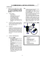
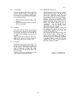
Figure 19 : LIGHTING THERMOELECTRIC
MODELS 25
→
45
Legend figure 19:
1 Control
knob
2 Governor
3
Inlet gas pressure test point
4
Burner pressure test point
5
Pilot gas throttle screw
6
Main burner electrical connection
7 Gas
inlet
8 Gas
outlet
9
Pilot gas line connection
10 Thermocouple
connection
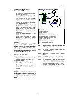
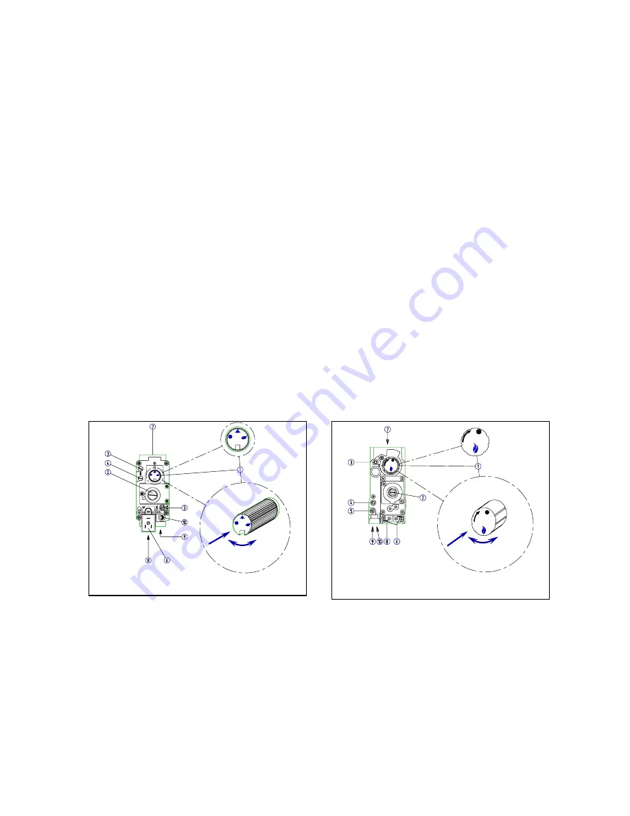
Figure 20 :LIGHTING THERMOELECTRIC
MODELS 55
→
95
Legend figure 20.
1. Operating
button
2. Gas
governor
3.
Inlet gas pressure test point
4.
Outlet/burner gas pressure test point
5.
Ignition burner gas throttle screw
6.
Main burner electrical connection
7.
Gas inlet connection
8. Gas
outlet
connection
9. Ignition
burner gas connection
10.
Thermocouple connection

