0501UCA
6/25
UCA
Model
Heat Input
kW
Room
Volume m³
25
30.28
142
30
34.94
165
35
43.26
203
45
52.00
245
55
64.67
304
75
88.96
418
95
118.70
558
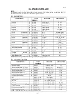
UCA
Model
Heat
input kW
Low
level
cm²
25
30.28
140
30
34.94
160
35
43.26
200
≤
60 kW
45
52.00
240
55
64.70
290
75
88.95
340
≥
60 kW
95
118.70
410
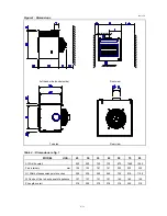
Table 3 : Dimensions re fig. 2
UCA
25
30
35
45
55
75
95
L minimum
550
620
750
900
1100
1400
L1 Opposite side
150
300
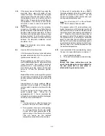
4. AIR SUPPLY for COMBUSTION & VENTILATION
4.1
It is essential that sufficient fresh air is provided
for combustion and room ventilation. Most
traditional building constructions have a natural
air change rate of at least 0.5/h. Where it is
known that the air change rate is at least 0.5/h
and where the volume of the heated space is
greater than 4.7m³ per kW of total rated heat
input, additional ventilation is not required.
4.2
Table 4.
Building volume limits for UCA air Heaters
based upon 4.7m
3
per kW of rated heat
input for one air heater only.
If the minima volumes stated above exist
together with appropriate similar allowances for
other combustion plant that may be installed in
the same space or zone, then additional
ventilation is not required.
4.3
Where it is known that the air change rate is less
than 0.5/h or where the building volume is less
than 4.7m³ per kW of heat input, ventilation
grilles must be provided at low level i.e. below
the level of the appliance flue connection. In
cases where doubt exists over the air change
rate ventilation should be provided.
For air heaters of heat input less than
60 kW the total minimum free area shall not be
less than 4.5 cm² per kW of total rated heat
input as table 5 below.
For our heaters of heat input 60 kW or more the
total minimum free area shall not be less than
270 cm² plus 2.25 cm² per kW in excess of the
60 kW rated heat input.
4.4
Table 5. Air Supply Requirement for
Combustion & Ventilation.
Note :
Ventilation grilles must be installed so
that air is drawn directly from outdoors. In the
event that communication from the space where
the heater is installed to outdoors is via another
room then the route to outdoors must be ducted
through the communication area.
The grille velocity for all air supply must not
exceed 2.0 m/s. Grilles should be sited where
they cannot easily be blocked or flooded.
Notices should be provided advising about the
need to keep air supply grilles unobstructed.
4.5 Where
mechanical
ventilation is used it shall be
by mechanical inlet with either mechanical or
natural extraction. Automatic means of control
such as interlocks must be provided. The
function of other ventilation plant in the zone
must be taken into account. At no time should it
be possible to create a negative pressure in the
zone as this will lead to a hazardous situation
whereby the air heater flue will act as a pressure
relief.
4.6
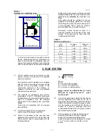
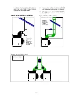
Normally UCA air heaters are installed within the
room or space to be heated. If it is necessary to
install the air heater in a separate room and
blow the air into an adjoining room, then a short
duct not exceeding 1,0 metre may be used to
connect the appliance to the air discharge louvre
as shown in figure 3.


