0501UCA
7/25
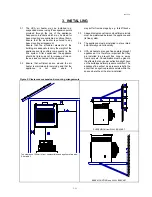
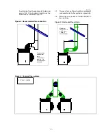
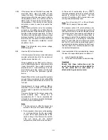
Maximum 1000 mm
Minimum 300 mm
→
→
RETURN AIR PATH
→
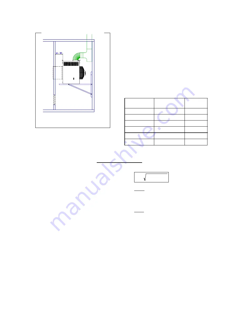
UCA
model
Air volume
m
3
/h
Grille size
CM
2
25
1 700
2 400
30
2 400
3 400
35 &45
3 700
5 200
55
4 200
5 900
75
5 600
7 200
95
7 900
11 000
Figure 3 :
Installing in an adjoining room
A return air grille must be provided to ensure
that an unobstructed path for recirculation; air
back to the air heater is maintained, this is to
ensure that a negative pressure cannot develop
within the space where the air heater is installed.
Grilles sized in accordance with table 6 must be
installed at
low level
. The sizes stated must be
regarded as the
minimum
free area size to be
fitted.
Such grilles should be situated as low as
possible in the dividing wall and in a location
where they are unlikely to become obstructed. It
is recommended that a guard be fitted to
prevent obstruction i.e. stored materials.
Permanent notices should be fixed in a
prominent location on either side of the grille
worded, "This grille must be kept clean and
unobstructed at all times".
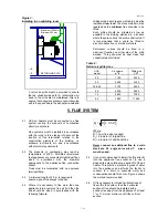
Table 6 :
Return air grille sizes
5. FLUE SYSTEM
5.1 UCA air heaters must be connected to a flue
system venting the products of combustion
directly to outdoors.
Flue systems must be installed in accordance
with the rules in force taking into account the
location of flue termination relative to the
construction elements of the building, i.e.
windows, roof levels, etc., and in accordance
with statutory requirements.
5.2 The products of combustion may reach a
temperature of 230°C. AmbiRad recommend
that appliances are connected to individual flues
sized in accordance with the diameter
appropriate to the appliance flue connection
socket.
Flues must be terminated with an approved
terminal fitting.
5.3
A minimum length of 2.0 m is required to
ensure a good flue draught condition.
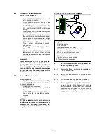
5.4 Where it is necessary to flue more than one
appliance into a common flue as fig.6 then the
flue should be sized in accordance with the
following formula:
D
0.5
+
D
=
D
2
3
2
2
1
Where
:
D
1
= new flue size required
D
2
= diameter of largest flue
D
3
= diameter of additional flue
Never
connect an additional flue to a main
stack at a 90 angle an inverted Y piece
must be used.
5.5
It is not recommended to install the flue directly
into the appliance flue socket but to use a
stopped tee piece following a bend off of the air
heater. This practice prevents ingress of water
into the appliance and affords the facility to
connect to a drain to evacuate water and
condensation should this occur. Figure 4 shows
the method recommended.
5.6
If it is necessary to include horizontal runs of
flue within the system, then the horizontal
section of flue should be installed with a
positive rise away from the appliance of at least
1° or 17 mm per metre run until the vertical
section.


