

www.amcelettronica.com
Installation Instructions
soutdoor L
R1
R2
TAMPER
ALARM
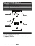
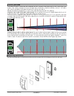
EOL terminal
It is possible to have different balaced value, see figure:
R1 tamper = 10K
R2 alarm contact =4K7
Not alarm=10K
Alarm = 14K7 (R1+R2)
Tamper = Open
R1 tamper = 5K6
R2 alarm contact =5K6
Not alarm=5K6
Alarm = 11K2 (R1+R2)
Tamper = Open
close
open
8K2
8K2
5K6
5K6
4K7
4K7
1K
2K2
R1
R2
5K6
5K6
4K7
10K
EOL open = N.C. alarm contact
EOL close = balanced enabled
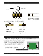
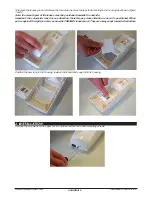
Board Adjustment
In addition to the electronic adjustments, the sensor can be vertically adjusted physically regarding the direction of the
beams. As you can see in the picture below you can slide the board inside the cover.
1 2 3 4 5 6
FUNCTIONS
Sliding system detail
board
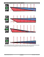
The sliding is opposite to the beam so when the board is moved up-
ward the beams are lowered and when it is lowered beams are raised.
In the figures below you can see the effect achieved when moving
the board. These adjustments are also needed for animal tolerance.
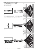
With the lens mounted by default (volumetric up, horizontal curtain
down) you can get a very accurate result on animal tolerance.
Test the sensor alarm threshold whenever an adjustment is made.
NOTE: sliding the board it must remain
/ - 2 mm. from centrally located for
not to compromise the sensor detection
EOL jumper configuration


