background image

www.amcelettronica.com

Installation Instructions

soutdoor L

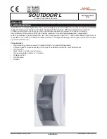
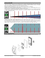
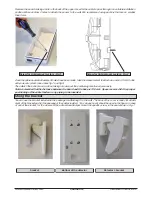
Remove the board, making a hole in the back of the upper cover for the cable to pass through in a suitable installation 

position. Make another 2 holes to attach the sensor to the wall. We recommend using anchors that are no smaller 

than 3 mm. 

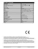
Once the cable and wall attachment holes have been made, take the measurement to attach an anchor (3 mm) to the 

anti-removal system. (see above fig.1 and fig.2)

Then attach the bottom and re-close, taking into account the positioning mentioned previously.

Note: remember that the distance between the board and the base is 13.5 mm. Space reserved for the proper 

positioning of the cable feeder or any piping to be inserted.

Screw for Anti-removal system - Fig.2
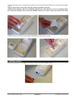
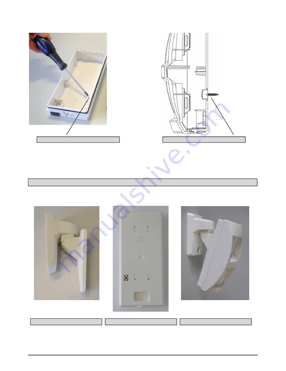
Using the bracket

You can use the bracket included in the package for attaching it to the wall. The back of the cover is ready for attach-

ment of the bracket and for the passage of the cables inside it. You can see how it should be used in the figure. In case 

of use of the bracket, for the closure of the anti-removal tamper mount the specific screw, in the seat shown in Fig.1.

bracket

Screw for Anti-removal system - Fig.1
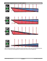
A    B

C    D

Bottom of the detector

De bracket

Summary of Contents for soutdoor L

Page 1: ...centage of false alarms With hight thermal variations the totally digital temperature compensation system guarantees a great performance Has 15mt coverage with angle of 90 With usable different type o...

Page 2: ...ed Dip switches EOL resistor jumpers Walk test LED anti opening height adjustment board Installation Place the sensor at a height of between 1 m and 2m Important placement should be chosen depending o...

Page 3: ...ing the direction of the beams As you can see in the picture below you can slide the board inside the cover FUNCTIONS Sliding system detail board The sliding is opposite to the beam so when the board...

Page 4: ...UNCTIONS 1 2 3 4 5 6 FUNCTIONS 1 2 3 4 5 6 FUNCTIONS Coverage diagrams based on board position Note the figures show the effect of the beams based on the position of the board Since they are purely in...

Page 5: ...ackage there are 3 types of lenses Horizontal curtain lens Fig 1 Vertical curtain lens fig 2 Volumetric curtain lens fig 3 On the sensors are mounted by default on the PIR1 top the volumet ric lens an...

Page 6: ...the beam range This way you have a variable height protection from 35 40 cm from the ground and up to 1 6 cm high with a horizontal coverage of about 80 100 degrees With this configuration you can ac...

Page 7: ...be positioned towards the outside Important the volumetric lens has one direction therefore pay close attention to how it is positioned When put up against the light you can see how the FRESNEL lenses...

Page 8: ...nt the positioning mentioned previously Note remember that the distance between the board and the base is 13 5 mm Space reserved for the proper positioning of the cable feeder or any piping to be inse...

Page 9: ...he manufacturer shall not be responsible if the product is tampered with by unauthorised persons We recommend that you check the correct operation of the alarm system at least once per month A reliabl...

Reviews: