C h a p t e r 4 S i n g l e T r a n s f e r F o r m a t
23
20 Gear Drive, Plymouth Ind. Park, Terryville, CT 06786
Tel: (860) 585-1254 Fax: (860) 584-1973
Single Transfer Definition
Single transfers are used by most non-intelligent I/O cards such as DC input cards. Single
transfers automatically move data between the module and the processor’s input or output image
tables every program scan. Immediate I/O instructions can also be used to update data during
the program scan. The 1761H module accepts and transmits 16 bits of data when in single
transfer mode.
When using 2-slot addressing, you must not install a card in the adjacent slot of
the slot pair. The 1761H module uses 16 input and 16 output bits. A power supply
card can be in the adjacent slot of the pair.
Single Transfer Input Format
When using a 1761H module in Single Transfer Mode, (Jumper J3-1 Removed), the position
data is written into the processors’ input table at the slot address assigned to the module. In
Single Transfer Mode, the setting of J3-2 (Binary/BCD data jumper) has no effect, the position
data is always written in binary. Table 4.1 shows AMCI and Autotech transducer position data.
Full Scale Number of Turns (fixed)
Counts per Turn
Total Counts
AMCI 100 Turn 25 1,000 25,000
AMCI 1,000 Turn
250
100
25,000
AMCI 180 Turn 30 1,000 30,000
AMCI 1,800 Turn
300
100
30,000
Autotech 128 Turn 32 1,000 32,000
Table 4.1 Position Data for AMCI and Autotech Transducers
Data Format
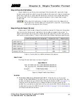
The Single Transfer data format is shown in figure 4.1.
Figure 4.1 Single Transfer Input Format
Fault Bit
F
-
Transducer, Reference or Module Fault, Bit 15
- When this bit is set, the decimal
number -32768 (8000h MSB set) is sent to the processor in place of the position value. The
module will indicate the type of fault on the front panel by indicator LED’s
transducer fault will clear itself once a working transducer is properly attached to the
module. If you encounter a module fault, cycle power to the module. If the fault remains, the
module must be returned to AMCI for repair.
See Table 2.6 on page 17 for more information
on LED patterns and their functions.
Input Word 0
Hex
15 Bit Position Data
F
Word
Octal
17 16 15 14 13 12 11 10 07 06 05 04 03 02 01 00
15 14 13 12 11 09 08 07 06 05 04 03 02 01
10 00

