C
ONFIGURATION
D
ATA
F
ORMAT
SMD34K User Manual
ADVANCED MICRO CONTROLS INC.
60
Data Format (continued)
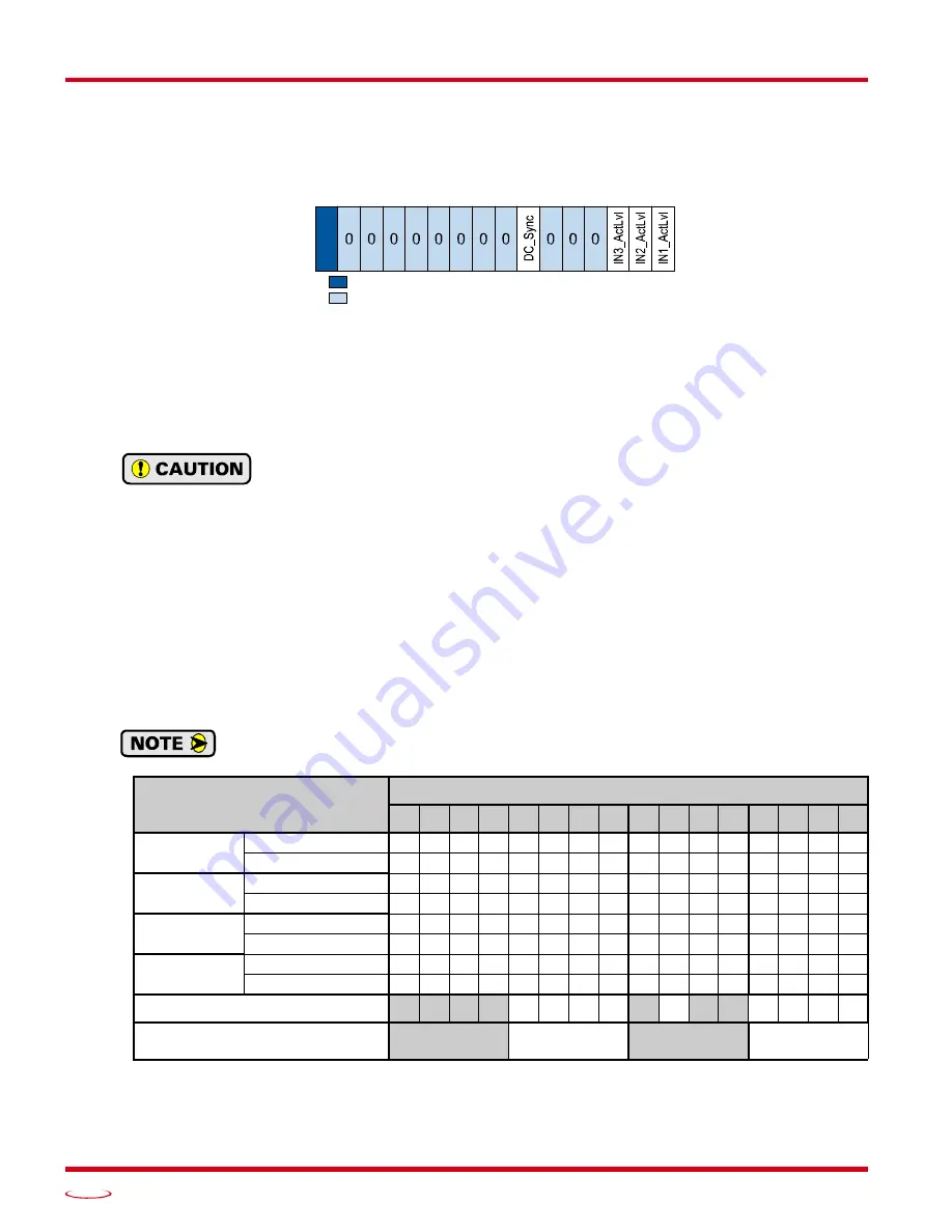
Configuration Word 1 Format
Figure R5.2 Configuration Mode: Config Word Format
Bit 15: Reserved –
State ignored.
Bits 14 - 7: Reserved –
Must equal zero.
Bit 6:
DC_Sync –
When set to “0”, the SMD34K begins a move as soon as data is read from the EtherCAT
Slave Controller (ESC). When set to “1”, the SMD34K will synchronize the move to the SYNC0 out-
put of the system’s Distributed Clock. This allows you to synchronize moves over multiple devices.
Input 3 is not available for use when using the Distributed Clock functionality. In these
cases, Input 3 must be left disconnected.
Bits 5 - 3: Reserved –
Must equal zero.
Bit 2:
IN3_Active_Level –
Determines the active state of Input 3. Set to “0” if your sensor has Normally
Closed (NC) contacts and the input is active when there is no current flow through it. Set to “1” if
your sensor has Normally Open (NO) contacts and current flows through the input when it is active.
Bit 1:
IN2_Active_Level –
Determines the active state of Input 2. Set to “0” if your sensor has Normally
Closed (NC) contacts and the input is active when there is no current flow through it. Set to “1” if
your sensor has Normally Open (NO) contacts and current flows through the input when it is active.
Bit 0:
IN1_Active_Level –
Determines the active state of Input 1. Set to “0” if your sensor has Normally
Closed (NC) contacts and the input is active when there is no current flow through it. Set to “1” if
your sensor has Normally Open (NO) contacts and current flows through the input when it is active.
If you are not using the input, sets its Active_Level bit to “1”. The input will always report as
inactive in the network data.
† Active Low: The SMD34K will report that the input is active when it is not conducting current.
Active High: The SMD34K will report that the input is active when it is conducting current.
Table R5.4 Configuration Word 1 Bits
...Set These Bits To
To Make These Settings...
15 14 13 12 11 10
9
8
7
6
5
4
3
2
1
0
Input 1
Active Low
†
0
Active High
†
1
Input 2
Active Low
†
0
Active High
†
1
Input 3
Active Low
†
0
Active High
†
1
DC_Sync
Disabled
0
Enabled
1
Resulting Bit Pattern:
0 0 0 0 0 0 0 0 0
0 0 0
Hexadecimal Digits for
CoE Configuration Setting:
0/
1
IGNORED: Bit can equal either value.
RESERVED: Bit must equal zero.
Configuration Word 1
15 14 13 12 11 10 09 08 07 06 05 04 03 02 01 00
Summary of Contents for SMD34K
Page 1: ...MICRO CONTROLS INC ADVANCED U s e r M anual Manual 940 0S280 ...
Page 6: ...TABLE OF CONTENTS SMD34K User Manual ADVANCED MICRO CONTROLS INC 6 Notes ...
Page 50: ...CALCULATING MOVE PROFILES SMD34K User Manual ADVANCED MICRO CONTROLS INC 50 Notes ...
Page 62: ...CONFIGURATION DATA FORMAT SMD34K User Manual ADVANCED MICRO CONTROLS INC 62 Notes ...
Page 80: ...COMMAND DATA FORMAT SMD34K User Manual ADVANCED MICRO CONTROLS INC 80 Notes ...
Page 100: ...LEADERS IN ADVANCED CONTROL PRODUCTS ADVANCED MICRO CONTROLS INC ...


