background image


20         

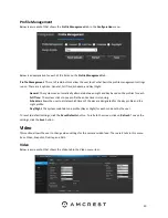
Profile Management  

Below is a screenshot that shows the 

Profile Management

 tab in the 

Configuration

 menu:        


Below is an explanation for each of the fields on the 

Profile Management

 tab: 


Profile Management

: This set of radio buttons allow the user to set what basis the profile management settings 

run on. There are 4 options: General, Full Time, Schedule, and Day/Night.  


General

: The system can automatically alternate between night and day based on the profiles for each.    

Full Time:

  The system sticks to one profile the entire time it is running.  

Schedule:

 allows the user to dictate which times of the day are designated for the day profile and the 

night profile.  

Day/Night

: The system maintains one profile (Day or Night) for each mode set by the user.        


To reset to default settings, click the 

Reset Defaults

 button. To refresh the screen, click on 

Refresh

. To save the 

settings, click the 

Save 

button.            


Video          

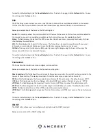
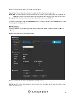
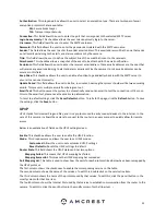
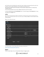
This section allows the user to change video settings for the camera’s video feed. There are 4 tabs in this menu 

item: Video, Snapshot, Overlay, and Path.          
  

Video 


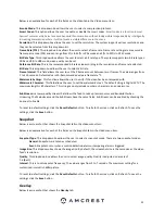
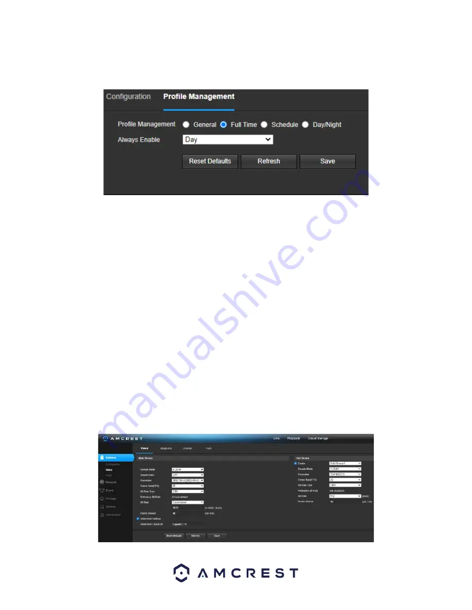
Below is a screenshot that shows the Video tab in the Video menu item:        


Summary of Contents for IP5M-T1273EB-AI

Page 1: ...Amcrest IP5M T1273EW AI IP5M T1273EB AI 5MP UltraHD POE Night Color AI Turret Camera User Manual Version 1 0 0 March 9th 2021...

Page 2: ...ce 13 Playback 14 Camera 16 Storage 45 Destination 48 System 51 Information 54 Alarm 55 Logout 56 Remote Web Access Setup 56 Amcrest Cloud Desktop Setup 58 Web Access Setup AmcrestView com 58 FAQs Tro...

Page 3: ...lt password for your camera Always ensure that your password is at least 810 characters long and contains a combination of lowercase characters uppercase characters as well as numbers Important Safegu...

Page 4: ...easy to use and can be viewed on a computer via the built in web user interface or on your smartphone using the Amcrest View Pro app This camera adopts a high quality design to achieve high levels of...

Page 5: ...for the physical installation of your camera What s Included The camera The Installation Bracket An Installation template sticker Pack of wall anchors and screws Ethernet cable protectors Tools neede...

Page 6: ...3 Align the holes on the installation bracket to the installation holes Also make sure to align the Front and Up portions of the bracket to the installation sticker Insert the screws and using a Phil...

Page 7: ...holes on the installation bracket to the installation holes Also make sure to align the Front and Up portions of the bracket to the installation sticker Step 4 Remove the side cable tray insertion pie...

Page 8: ...the first time or you are setting up your camera for mobile viewing Using the Amcrest Cloud app or Amcrest View app on your smartphone or tablet you can view your camera live from anywhere and access...

Page 9: ...est Cloud app setup You can register for a cloud account in the Amcrest Cloud app or from the Amcrest Cloud website at amcrestcloud com Please make sure your camera is plugged into a power source and...

Page 10: ...l automatically detect that a new camera is being added Tap OK to proceed 7 Set a new password for your camera The password must be between 8 to 32 characters long and contain only letters and numbers...

Page 11: ...these steps The following steps will continue the app setup process for an Android phone and though the iPhone version of the app has slightly different steps most of this process is identical and eas...

Page 12: ...visit amcrest com support 6 Scan the QR code The QR code can be found on the serial tag along with a scannable barcode 7 Create a name for the device and enter a username and password The default use...

Page 13: ...click on IP Config Software to begin the free download Once the download has completed installing locate the IP address associated with the device you would like to view in the browser Open a web bro...

Page 14: ...a Section 4 This section allows the user to access setup options alarms and logout the interface Section 5 This option allows the user to take a snapshot of the live view screen Playback The Playback...

Page 15: ...selected from the file list use the play and stop button to play or stop the recording An additional slider option will be displayed by hovering the mouse pointer over the playback interface Section 5...

Page 16: ...lows the user to change between specific settings configurations 3 Menu Tab Displays different tabs related to a selected menu option Camera This menu tab allows the user to change different camera se...

Page 17: ...ecommended value ranges from 40 to 60 Sharpness This slider is used to adjust the sharpness of the video The value ranges from 0 to 100 The larger the value is the clearer the edges are and vice versa...

Page 18: ...ttings from the target area HLC Highlight compensation is a feature that came out of necessity due to overexposure from strong light sources like headlights or spotlights WDR Wide Dynamic Range makes...

Page 19: ...ify The 3 options are Day Night and Normal Mode This dropdown box allows the user to select whether to turn the color night vision spotlights on or off General Sets the spotlights to automatically tur...

Page 20: ...r each Full Time The system sticks to one profile the entire time it is running Schedule allows the user to dictate which times of the day are designated for the day profile and the night profile Day...

Page 21: ...erify if the video has been tampered with Watermark Character This field allows the user to set the watermark s text The default string is Digital CCTV The maximum length is 85 characters This string...

Page 22: ...e button To remove all privacy filter boxes click the remove all button To remove all the settings applied in this menu click Remove All To delete a specific setting select the setting you wish to del...

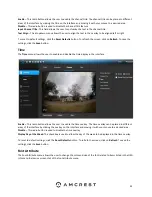
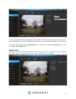
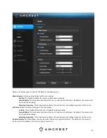
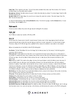
Page 23: ...e button Time The Time menu allows the user to enable and disable the time display in the interface Enable This radio button allows the user to enable the time overlay The time overlay can be placed i...

Page 24: ...to 64 64 48 48 32 32 16 16 sizes To reset to default settings click the Reset Defaults button To refresh the page click the Refresh button To save the settings click the Save button Logo Overlay This...

Page 25: ...stom overlay click on the enable radio button Enter the custom text into the Input Custom OSD box and use the Text Align dropdown box to align the text To enter multiple custom overlays click on the o...

Page 26: ...user to select a sampling frequency for the audio Sub Stream Sets the audio settings for the sub stream Enable This checkbox allows the user to enable audio recording Encode Mode This dropdown box all...

Page 27: ...have options to pick either of the connections The Set as Default button allows the user to select one of the connection methods as the default one Mode Static vs DHCP This radio button allows the use...

Page 28: ...the Reset Defaults button To refresh the page click the Refresh button To save the settings click the Save button Connection The Connection tab is where users can configure port connections Below is...

Page 29: ...use this feature users will need to setup an account with a DDNS service The camera supports a variety of DDNS services such as AMCRESTDDNS NO IP DDNS CN99 DDNS and Dyndns DDNS Based on which service...

Page 30: ...ows the user to remove all sites from the trusted IP MAC list To reset to default settings click the Reset Defaults button To refresh the page click the Refresh button To save the settings click the S...

Page 31: ...est This button causes the system to automatically send out an email to test the connection is OK or not Prior to the email test please save the email setup information To reset to default settings cl...

Page 32: ...et to default settings click the Reset Defaults button To refresh the page click the Refresh button To save the settings click the Save button HTTPS Hypertext Transfer Protocol Secure https is a combi...

Page 33: ...ther This field allows the user to set the anti dither time The values in this field can range from 5 to 600 seconds This time value controls how long the alarm signal lasts Based on motion detection...

Page 34: ...for motion detection After the motion detection zone is set click the enter button to exit the motion detection screen Remember to click the save button on the motion detection settings screen otherw...

Page 35: ...ettings Below is a screenshot of the Video Tamper tab Below is an explanation of the fields on the Video Tamper tab Enable This checkbox enables a video tamper alarm for the camera Schedule Clicking t...

Page 36: ...era when a video tamper alarm is triggered Alarm Delay This field specifies in seconds how long the delay between alarm activation and Relay alarm activation should be Send Email This checkbox allows...

Page 37: ...on the bottom half of the screen There are a total of 6 periods that can be set 93 Anti Dither This field allows the user to set the anti dither time The values in this field can range from 5 to 600...

Page 38: ...the Save button Smart Plan A smart plan acts as the master switch for all AI features available in your camera Below is a screenshot of the Smart Plan menu To refresh the menu to its original format c...

Page 39: ...n Schedule Allows the user to set a schedule in which the IVS rule will be triggered Direction This dropdown menu allows the user to set which direction the object will be going for the tripwire to be...

Page 40: ...et a name for the rule by double clicking the mouse over the Name of the rule 2 Click on Setup to set a schedule set your periods if any and click Save to continue 3 In the Direction menu choose which...

Page 41: ...nters exits a set line or area Object filter The object filter checkboxes allow the camera to be triggered only when a specific object such as a human or car is detected by the camera Both effective o...

Page 42: ...3 In the Action menu choose whether the rule will be triggered if an object appears or crosses the set region Both options can be enabled at the same time if needed 3 In the Direction menu choose if...

Page 43: ...lay This field specifies in seconds how long the delay between events should be The default is 10 seconds however this can be modified between 10 300 seconds Relay Out This checkbox allows the user to...

Page 44: ...apacity Warning Enable This checkbox enables the SD Card abnormality trigger for the camera Send Email This checkbox allows the user to enable the camera to send an email when an SD Card abnormality i...

Page 45: ...legal Access related abnormality Below is a screenshot of the Illegal Access tab screen Below is an explanation of the fields on the Illegal Access settings tab Enable This checkbox enables the Illega...

Page 46: ...the color yellow Alarm Alarm recording means that the camera captures only footage when an alarm is activated Alarm recording is represented by the color red Video Recording Schedule To specify a vide...

Page 47: ...nge first select the type of snapshot desired then click and drag on time bar for the desired date To edit multiple days at once drag the cursor further up or down to cover the other days Setup Clicki...

Page 48: ...hot of the Path tab Below is an explanation of the fields on the Path settings tab Event Type This column designates storage options available to the camera The options are SD Card FTP and NAS Schedul...

Page 49: ...n of the fields on the FTP settings tab Enable This checkbox allows the user to enable FTP uploading for the camera s recorded media Server Address This field allows the user to designate a DDNS addre...

Page 50: ...ote Directory This field allows the user to specify a remote directory on the NAS to send the recorded media to To reset to default settings click the Reset Defaults button To refresh the page click t...

Page 51: ...his menu redirects the user to the Amcrest Cloud web site At this website amcrestcloud com users can register for new accounts as well as view or modify existing accounts For more information on Amcre...

Page 52: ...the port number for the NTP server Update Period This field allows the user to enter in the update period time This number designates how frequently the camera pings the NTP server to ensure it has th...

Page 53: ...Maintain This screen allows the user to set auto maintenance settings for the camera Below is a screenshot of the Auto Maintain screen Below is an explanation of the fields on the Auto Maintain screen...

Page 54: ...e various information about the camera s software versions as well as other information On this screen software version web interface version and ONVIF version are displayed Also the S N Token ID is d...

Page 55: ...of the Online Users screen Click Refresh to refresh this table Alarm This screen is where the alarm log is kept Below is a screenshot of the alarm screen The table on the right shows the alarm log an...

Page 56: ...ensure that the HTTP port has changed 7 Click the DDNS menu item on the left hand menu pick Amcrest DDNS from the drop down box click the checkbox next to Server Type and then click the Save button on...

Page 57: ...long to prevent any port conflicts If need be change each of these port numbers to a 5 digit number that is less than 65535 note the numbers down and click save before proceeding to the next step 11 G...

Page 58: ...d storage 4 View your camera live or watch recorded clips using the menu button on the top of the page You can also use the Amcrest Cloud app on iOS and Android to add more cameras play recordings and...

Page 59: ...g into your camera s web user interface via a laptop or PC Navigate to Setup System General Click on the Date Time tab Click on PC Sync to sync the date and time Click Save to save and apply the new d...

Page 60: ...are a few possible reasons why this may be occurring The media player software on the PC may not be able to read the file format The PC may not have DirectX 8 1 or higher The PC may not have Windows...

Page 61: ...paration distance of at least 20 cm from all persons and must not be co located or operating in conjunction with any other antenna or transmitter End users and installers must be provided with antenna...

Page 62: ...in the parts is above the relevant threshold of the SJ T11363 2006 standard During the environmental friendly use period EFUP period the toxic or hazardous substance or elements contained in products...

Reviews: