68
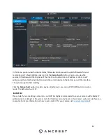
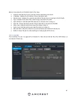
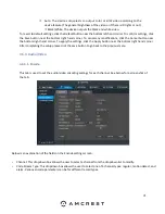
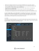
Below is an explanation of the fields listed in this menu:
•
Channel: Indicates the channel number of the camera being monitored.
•
Status: Indicates the connection status of the camera. It can be either green, for good connection, or red, for
possible connection issue.
•
IP Address: Indicates the IP address of the connected camera.
•
Port: Shows which port number the camera is connected to.
•
Manufacturer: Indicates the current protocol that the camera is connecting to the NVR with.
•
Device Type: Indicates the model of the camera being connected to the NVR.
•
System Version: Indicates what firmware version the camera is running on.
•
Update Status: Allows the user to see if the firmware needs to be updated. If the firmware for the camera needs
to be updated the system will say, “
To be upgraded”
.
Important
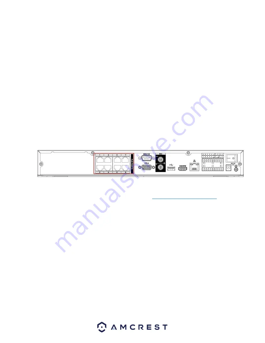
Do not connect a switch to the PoE port, otherwise the connection may fail!
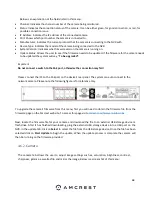
Please connect the IPC to the PoE port on the device’s rear panel. The system can auto connect to the
network camera. Please note the following figure is for reference only.
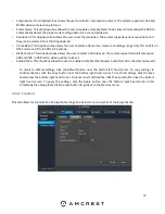
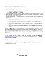
To upgrade the camera’s
firmware from this menu, first you will need to obtain the firmware file from the
firmware page on the Amcrest web site. To access this page visit
amcrest.com/firmware-subscribe
Next, locate the firmware file for your camera and download the file to an external USB storage device or
flash drive. After it has finished downloading, plug the external USB storage device into a USB port on the
NVR. In the update tab, click on
Select
to select the file from the USB storage device. Once the file has been
selected click on
Start Update
to begin the update. When the update process is complete the camera will
then be running on the firmware provided.
4.6.2.
Camera
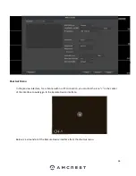
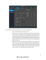
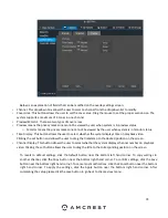
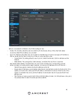
The camera tab allows the user to adjust image settings such as, saturation, brightness, contrast,
sharpness, gamma, as well as flip and mirror the image. Below is a screenshot of this menu:
Summary of Contents for NV21 Series
Page 1: ...Network Video Recorder User Manual Version 1 0 4 Revised November 21st 2018 ...
Page 201: ...201 Figure 5 39 5 9 2 7 Email The email interface is shown as in Figure 5 40 ...
Page 214: ...214 Figure 5 58 ...
Page 227: ...227 Figure 5 77 Figure 5 78 ...
Page 245: ...245 Figure 5 102 5 10 2 Log Here you can view system log See Figure 5 103 Figure 5 103 ...

