103
HELIX™
Manual (P/N 26291)
Chapter 6: Recharge
Rev A (February 2018)
HELIX™
PCU Fire Suppression System
6.2.8 Pneumatic Actuation Network Testing
For systems using a Pneumatic Actuation Network, perform the following steps. After connecting all
control heads and actuators to the Pneumatic Actuation Network, the network must be tested for
functionality and leaks. If multiple actuators are used along with Check Valves, each actuator and
independent leg of the Pneumatic Actuation Network must be tested separately.
1.
Before proceeding, all control heads must be removed from Agent Cylinders, and all
Nitrogen Cylinders must be removed from actuators. Disconnect the electrical
connector for any 50 psi Pressure Switches.
2.
Install the Actuation Network Test Adapter (P/N 10895) into the actuator body in place of the
Nitrogen Cylinder (See Figure 6.1.6).
3.
Pressurize the Pneumatic Actuation Network through the Actuation Network Test Adapter using
dry air or nitrogen at 80
-
90 psi (551
-
620 kPa).
4.
Verify that each piston in each control head actuates. Pistons equipped with a Locking Plunger
should lock in the open or actuated position.
5.
Verify that each component and connection in the Pneumatic Actuation Network has no leaks.
6.
To relieve pressure in the Pneumatic Actuation Network, unseat the Vent Check(s) (P/N 10173
-
R) on the control head(s). After all pressure is relieved, reinstall Vent Check.
7.
Reset all control head pistons to their fully recessed positions. If equipped, depress the Spring
Plungers per Section 6.2.1.
8.
If multiple actuators are used in a Pneumatic Actuation Network, repeat steps 2 though 7 for
each actuator.
9.
After verifying that all
components are functioning properly and no leaks are present, reinstall
control heads on Agent Cylinders per Section 4.3.2 and Nitrogen Cylinders in actuators per
Section 4.5. Reconnect the electrical connector for any 50 psi [344 kPa] Pressure Switches per
Section 4.4.
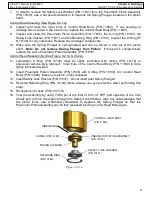
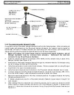
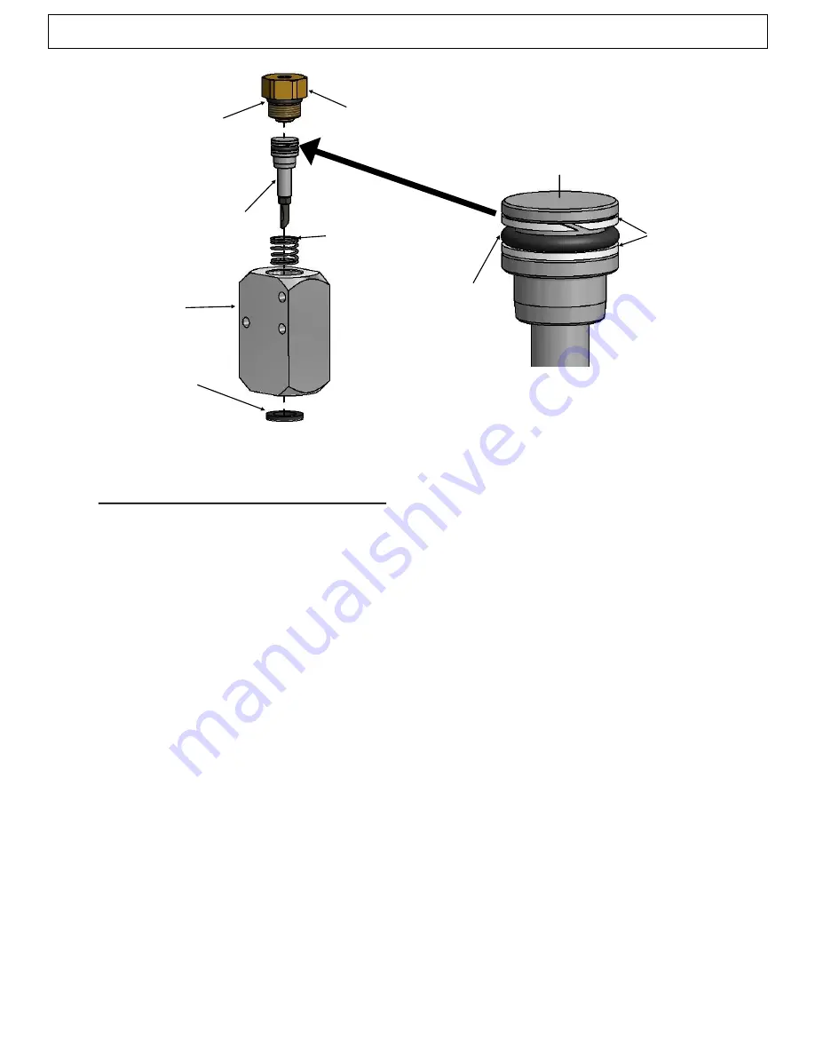
ADAPTER (P/N 20458)
SPRING (P/N 10097)
PUNCTURE STEM ASSEMBLY
(P/N 22873)
(INCLUDES O
-
RING AND
BACKUP RINGS (2))
O
-
RING (P/N 10513)
INCLUDED IN
REBUILD KIT
(P/N 10939)
ACTUATOR BODY
(P/N 20774)
Figure 6.2.7
GASKET (P/N 07247)
O
-
RING (P/N 09989)
INCLUDED IN
REBUILD KIT
(P/N 10939)
BACK
-
UP RINGS
(P/N 09993)
INCLUDED IN
REBUILD
KIT (P/N 10939)

