107
HELIX™ Manual
(P/N 26291)
Chapter 7: System Alarms & Troubleshooting
Rev A (February 2018)
HELIX™ PCU
Fire Suppression System
Chapter 7: System Alarms & Troubleshooting
The Amerex STRIKE Electronic Control System (ECS), under normal working conditions, will display
the green “System Normal” LED on the STRIKE Control Unit by flashing once approximately every 4
seconds. If the green “System Normal” LED is not flashing, an alarm or trouble condition exists with
the system.
Any alarm or trouble condition shown on the
STRIKE
Control Unit mandates
performing the Battery Replacement Procedure (See Section 5.6).
7.1 System Alarm Condition
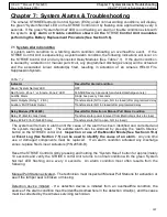
A system alarm condition is a latching alarm condition indicating an overheat/fire event. If the
STRIKE Control Unit is experiencing a system alarm condition, the following indications will occur on
the STRIKE Control Unit and any connected Relay Modules (See Table 7.1). If the alarm condition
is caused by a detection or manual pull circuit, any programmed discharge zone(s) will be actuated
and the associated Linear
Actuator(s) fired, resulting in actuation of an Amerex HELIX Fire
Suppression System.
The
system will remain in alarm until the cause of the alarm has been identified and corrected and
the system manually reset. The audible alarm can be silenced by pressing the ‘Alarm Silence’
button on the STRIKE Control Unit.
Inspection or use of the Monitor Mode (See Section 4.10.4)
or Event Log (See Section 7.5) can be used to identify the cause of an alarm.
Any one time
use or damaged components must be replaced. If an alarm condition actuated any discharge
zones, replace fired Linear Actuators (P/N 20500
-
R).
Reset the STRIKE Control Unit by pressing and holding the “System Reset” button for approximately
10 seconds and verify the STRIKE Control Unit returns to normal condition with the green ’System
Normal’ LED flashing once every 4 seconds. An alarm condition most often results from the
following:
Manual Pull Station activated
-
The technician must inspect all Manual Pull Stations for activation or
see if the tamper seal is broken or missing.
Detection device initiated
-
If a detection device is initiated from an overheat/fire condition, the
source of the alarm condition must be identified somewhere in the detection circuit(s), and the cause
must be corrected by the Amerex servicing technician.
Indicator
Result After Alarm Condition
Green ‘System Normal’ LED
OFF
Red ‘Alarm– Zone 1’ or ‘Alarm– Zone 2’ LED
FLASHES every 3 seconds for actuated discharge zone(s)
Audible Alarm
Single beep every 3 seconds
Alarm Outputs (Relay 1, 2 & 3)
Transfers state (NC to open; NO to closed) after programmed delay
Auxiliary FACP Alarm Output
Transfers state (NO to closed) after programmed delay
Relay Module (P/N 24695)
Result After Detection or Manual Pull Alarm Condition
Relay #1 (Electric Gas Valve)
Transfers state (power removed from Electric Gas Valve to close)
Relay #2 & #3 (for P/N 24695 only)
Transfers state (NC to open; NO to closed)
Table 7.1

