22
HELIX™ Manual
(P/N 26291)
Chapter 2: System Components
Rev A (February 2018)
HELIX™
PCU Fire Suppression System
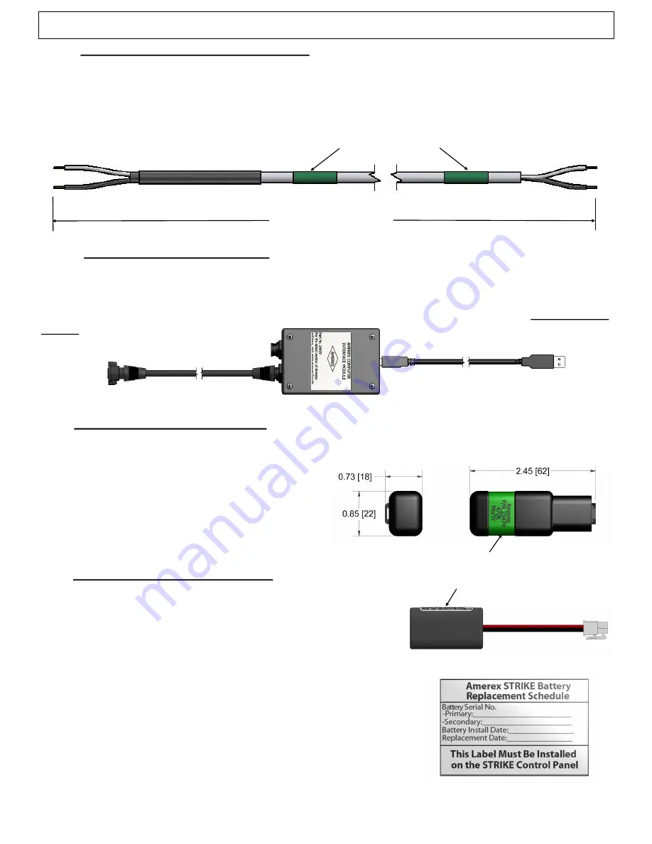
Figure 2.10.6
USB
TO PC
INTERFACE
PORT
2.11 End Of Line Module (P/N 23474)
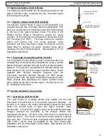
The End Of Line Module (EOL) is utilized to supervise circuitry and installed on the end of the Class
B detection circuits and manual pull circuit. The device provides a continuous electrical circuit
allowing for supervision of the normally open
detection network
. Three EOL modules are
supplied with each STRIKE Control Unit: two for
detection circuits and one for the manual pull
circuit. The EOL is color coded green
.
GREEN COLOR CODED
2.12 Replacement Battery (P/N 24903)
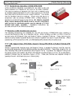
The STRIKE Control Unit is equipped with two batteries, a
primary and secondary, capable of sustaining normal operating
condition of the electronics for up to 6 months, after which a
Replacement Battery
is required. These additional
Replacement Batteries are supplied with a battery identification
label located on each (See Figure 2.12a), which displays the
Amerex part number, serial number, and battery description.
An additional battery replacement label is also supplied with
each battery and must be populated and applied during
installation of a Replacement Battery (See Figure 2.12b).
Specific battery replacement instructions and directions for
installing this label are described in Section 5.5. The
Replacement Batteries are UN/DOT compliant for shipping
purposes and must be stored in a clean, cool (86ºF/30ºC max),
and dry environment. Replacement battery shelf life is 10 years.
Figure 2.12b
BATTERY IDENTIFICATION LABEL
Figure 2.12a
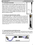
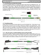
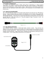
2.10.5 Communication Cable (P/N 25264
-
XX)
The Comm
unication Cable is an optional cable used with the STRIKE ECS to receive an alarm
signal from another STRIKE Unit or external Fire Alarm Control Panel (FACP). The cable is wired
from a normally open output (closed in alarm) of another STRIKE Unit or FACP into the detection
circuit of the STRIKE ECS. The Cable contains a built
-
in EOL resistor
as required by the Class B
detection circuit. Various lengths of each cable are available and shown in the Parts List (See
Section 2.16).
LENGTH (SEE PARTS LIST)
(P/N 25264
-
XX)
GREEN COLOR CODED
BLUNT
CUT
WIRES
BLUNT
CUT
WIRES
Figure 2.10.5
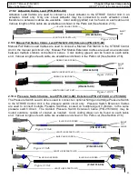
2.10.6 PC Interface Cable (P/N 16609)
The PC Interface Cable is used with the STRIKE PC software to program a system configuration,
view Monitor Mode, or download the Event Log on the STRIKE ECS. The cable connects the PC
Interface Port on the STRIKE Control Unit to the USB port of a laptop computer or PC. The latest
version of STRIKE PC software
is available on, and can be downloaded from the www.amerex
-
fire.biz website.
Figure 2.11

