1
HELIX™ Manual
(P/N 26291)
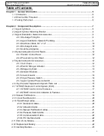
Table of Contents
Rev A (February 2018)
HELIX™ PCU
Fire Suppression System
Table of Contents
:
Chapter 1: General Information
...............................................................................................
5
1.1 Introduction
................................................................................................................
6
1.2 What Can Be Protected
..............................................................................................
6
1.3 Testing Performed
......................................................................................................
6
Chapter 2: Component Description
........................................................................................
7
2.1 Agent Cylinders
..........................................................................................................
8
2.2 Agent Cylinder Mounting Bracket
................................................................................
9
2.3 Agent Distribution Network Accessories
.....................................................................
9
2.3.1 Discharge Fitting Kit
..........................................................................................
9
2.3.2 Agent Distribution Network Plumbing
................................................................
9
2.3.3 Distributor Block 3/4” x 1/2”
...............................................................................
10
2.3.4 Discharge Nozzle
..............................................................................................
10
2.3.5 Quik Seal Adaptors
...........................................................................................
11
2.4 System Actuation Control Heads
................................................................................
12
2.4.1 Electric Control Head
........................................................................................
12
2.4.2 Pneumatic Control Head
...................................................................................
12
2.5 System Actuation Accessories
....................................................................................
12
2.5.1 Vent Check
........................................................................................................
12
2.5.2 Electric Nitrogen Actuator
..................................................................................
13
2.5.3 Nitrogen Cylinder
...............................................................................................
13
2.5.4 Actuator Brackets
..............................................................................................
13
2.5.5 Linear Actuator
..................................................................................................
14
2.5.6 50 psi Pressure Switch
......................................................................................
14
2.5.7 Agent Cylinder Pressure Switch
........................................................................
14
2.6 Dry Chemical Suppression System Parts List
...........................................................
15
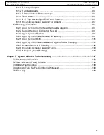
2.7 STRIKE Electronic Control System (ECS)
..................................................................
16
2.7.1 STRIKE
Control Unit & Enclosure
.....................................................................
17
2.7.2 STRIKE
Control Unit Indicators & Features
.......................................................
18
2.8 Manual Pull Stations
..................................................................................................
19
2.9 Linear Heat Detector
..................................................................................................
20
2.10 Field Wiring Cables
...................................................................................................
20
2.10.1 Detection Cables
............................................................................................
20
2.10.2 Actuation Cable
..............................................................................................
21
2.10.3 Manual Pull Station Cables
............................................................................
21
2.10.4 Pressure Switch Cable
...................................................................................
21
2.10.5 Communication Cable
....................................................................................
22
2.10.6 PC Interface Cable
.........................................................................................
22
2.11 End of Line Module
....................................................................................................
22
2.12 Replacement Battery
..................................................................................................
22
2.13 Auxiliary Devices
........................................................................................................
23

