29
HELIX™ Manual
(P/N 26291)
Chapter 3: System Design
Rev A (February 2018)
HELIX™ PCU
Fire Suppression System
Chapter 3: System Design
This Chapter describes system design and installation parameters of the Amerex HELIX Fire
Suppression System, including suppression, electrical detection and actuation, and any auxiliary
components.
3.1 Steps to System Design
•
Determine the quantity of nozzles required based on the PCU size and number of filter banks.
•
Determine the quantity of Agent Cylinder(s) and network configuration(s) required.
•
Determine the appropriate actuation method and required control heads.
•
Determine the STRIKE ECS electrical system
design, including the required detection (LHD)
lengths and attachment methods. Determine all required electrical circuits and cable lengths.
3.2 Nozzles
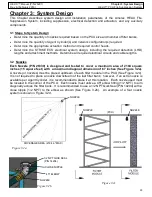
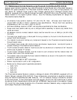
Each Nozzle (P/N 26330) is designed and tested to cover a maximum area of 2184 square
inches (15 square feet) with a maximum diagonal dimension of 67 inches (See Figure 3.2a).
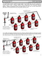
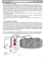
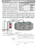
A nozzle (or nozzles) must be placed upstream of each filter module in the PCU (See Figure 3.2c).
It is not required to place a nozzle downstream of the last filter bank; however, if an extra nozzle is
available per Agent Cylinder, it is recommended to place it at this location. Each nozzle used must
be located in the corner of the PCU. Each nozzle must utilize a 45º elbow fitting (1/2 NPT) to aim
diagonally across the filter bank. It is recommended to use a 1/2 NPT Quik Seal (P/N 14204) with a
close nipple (1/2 NPT) to the elbow as shown (See Figure 3.2b). An example of a four nozzle
system is shown in Figure 3.2d.
Figure 3.2b
Figure 3.2c
AIR FLOW
COVERAGE AREA (2184 in² MAX)
Figure 3.2a
NOZZLE
NOZZLE
NOZZLE
(PCU)
45º ELBOW
CLOSE NIPPLE
1/2 NPT QUIK SEAL
(P/N 14204)
NOZZLE

