background image

 32


HELIX™ Manual 

(P/N 26291) 


Chapter 3: System Design


 Rev A (February 2018)


HELIX™ PCU 

Fire Suppression System


LOCATION


HOSE I.D.


in (mm)


HOSE LENGTH


ft (m)


NUMBER OF ELBOWS PER 

SECTION OF HOSE 


MAXIMUM


MINIMUM


MAXIMUM


MINIMUM


Cylinder to T1


3/4 (19.1)


45 (13.7)


5 (1.5)


2


0


T1 to each Nozzle 


1/2 (12.7)


15 (4.6)


2*


0


Cylinder to any 


Nozzle


60 (18.3)


5 (1.5)


All 1/2” hose 


30 (9.1)


All 3/4” hose


45 (13.7)


5 (1.5)


Table 3.4.1


Note: 

Hose  length  may  be  unbalanced  in  a  maximum  ratio  of  3:1  where  the  Agent  Distribution 

Network  splits  (T1  to  Nozzle).  However,  this  ratio  must  be  observed  for  the  minimum  versus 
maximum hose length.  Example: If the longest 1/2 inch I.D. hose leading from where the network 
splits (T1 to Nozzle) is 15 feet, the shortest 1/2 inch I.D. hose leading from the same network split 
location cannot be less than 5 feet, and all 1/2 inch I.D. hoses together  must fall within the length 
specified. 


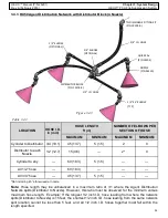
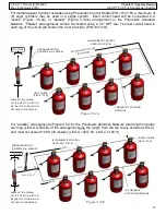
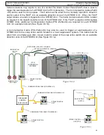
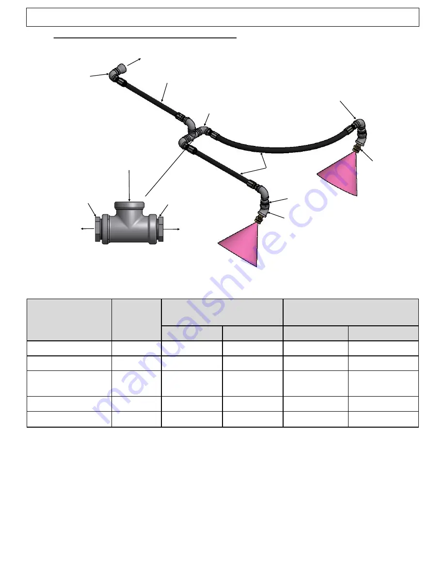
3.4.1  HX25  Agent Distribution Network (2 Nozzle)


Figure 3.4.1


1/2” I.D. HOSE 


1/2” ELBOW 
(TYP)


1/2” ELBOW


3/4” ELBOW
(OPTIONAL)


3/4” I.D. HOSE 


T1*  = 3/4” NPT TEE


TO NOZZLE


TO NOZZLE


3/4”

-

1/2” NPT 

REDUCER


3/4”

-

1/2” NPT


FROM AGENT 

CYLINDER


TO DISCHARGE FITTING KIT


 (P/N 10199

-

R)


T1*


NOZZLE      
(P/N 26330)


QUIK SEAL     
(P/N 14204)


1/2” 45° ELBOW 
(TYP) 


*Not including 45° elbow used at nozzle


Summary of Contents for HELIX

Page 1: ...rvice amerex fire com Technical Service Phone 205 655 3271 tech services amerex fire com AMEREX CORPORATION P O Box 81 7595 Gadsden Highway Trussville AL 35173 www amerex fire com POLLUTION CONTROL UNIT PCU FIRE SUPPRESSION SYSTEM DESIGN INSTALLATION MAINTENANCE RECHARGE MANUAL ...

Page 2: ... 6 3c 3 6 3d and associated bold wording 4 3 1 Revised Step 6 and added Figure 4 3 1b 4 5 Revised step 2 Linear Actuator Install Revised Figure 4 5b 4 7 3 Revised Figure 4 7 3a to show indoor outdoor installations 4 7 5 Added P N 26427 Added views 4 7 5d e f for outdoor installations 4 8 1 Revised View 4 8 1a 4 8 1b to show option of junction conduit box 4 8 2 Revised Step 1 Revised Figure 4 8 2 t...

Page 3: ... Pneumatic Control Head 12 2 5 System Actuation Accessories 12 2 5 1 Vent Check 12 2 5 2 Electric Nitrogen Actuator 13 2 5 3 Nitrogen Cylinder 13 2 5 4 Actuator Brackets 13 2 5 5 Linear Actuator 14 2 5 6 50 psi Pressure Switch 14 2 5 7 Agent Cylinder Pressure Switch 14 2 6 Dry Chemical Suppression System Parts List 15 2 7 STRIKE Electronic Control System ECS 16 2 7 1 STRIKE Control Unit Enclosure ...

Page 4: ...tion Network with Distributor Block 4 Nozzle 34 3 5 System Actuation Design 35 3 5 1 Single or Dual Agent Cylinder Networks with Electric Control Heads 35 3 5 2 Multiple Agent Cylinder Networks Pneumatic Control Heads 36 3 6 STRIKE ECS System Design 38 3 6 1 Introduction STRIKE ECS 38 3 6 2 Detection Circuit Design 42 3 6 3 Actuation Circuit Design 44 3 6 4 Manual Pull Circuit Design 45 3 6 5 Pres...

Page 5: ...Optional Device Circuits 72 4 9 STRIKE Control Unit Wiring Termination 74 4 10 STRIKE Control Unit Programming 77 4 10 1 Temporary Power Supply Connection 77 4 10 2 PC Software Installation Interface Connection 78 4 10 3 Programming a System Configuration 79 4 10 4 Monitor Mode 83 4 11 Function Testing Initial Commissioning 84 4 11 1 STRIKE Control Unit Display Testing 84 4 11 2 Detection Sensor T...

Page 6: ... Cleaning 96 6 2 2 Purging the Agent Distribution Network 99 6 2 3 Agent Cylinder Removal 99 6 2 4 Agent Cylinder Valve Removal Cleaning 99 6 2 5 Agent Cylinder Refill 101 6 2 6 Agent Cylinder Valve Installation Agent Cylinder Charging 101 6 2 7 Actuator Removal Cleaning 102 6 2 8 Pneumatic Actuation Network Testing 103 6 2 9 Nitrogen Cylinder Recharge 104 Chapter 7 System Alarms Troubleshooting 1...

Page 7: ...ns and use of the Amerex HELIX Dry Chemical PCU Fire Suppression Systems are limited to the applications and uses described in this manual Technical data contained herein is based on controlled laboratory testing deemed appropriate and is intended for informational purposes only The data presented is accurate for the testing performed but is published with no guarantee relative to a given hazard w...

Page 8: ...hemical Agent is discharged into hazard areas via an Agent Distribution Network consisting of flexible hydraulic hose The available Agent Cylinders with the number of supported nozzles are listed in Table 3 3 1 2 What Can Be Protected A complete PCU analysis must be performed for each piece of equipment being protected to determine the components that would require fire suppression by the Amerex H...

Page 9: ...us sizes and capacity and the Cylinder Brackets used for mounting each Agent Cylinder Also included are the components that comprise the Agent Distribution Network the Nozzles used for dispersing the Dry Chemical Agent and various control heads and accessories used to actuate and discharge the Agent Cylinders MANUAL PULL STATIONS RELAY MODULE STRIKE ECS DETECTION ACTUATION DISCHARGE NETWORK DETECT...

Page 10: ... GAUGE AGENT CYLINDER VALVE RUPTURE DISC UNDER CAP DUST CAP P N 25685 AGENT CYLINDER PRESSURE SWITCH 2 1 Agent Cylinders The Amerex HELIX Fire Suppression System Agent Cylinders are available in two sizes with different mounting options and orientations The Agent Cylinders are shipped fully charged from the factory Each Agent Cylinder includes a brass Agent Cylinder Valve with a Pressure Gauge and...

Page 11: ... 12 7 mm and 3 4 19 1 mm wire braided rubber hydraulic hose and the corresponding fittings Distribution hose and fittings are installer supplied Detailed specifications for these hoses by manufacturer are given in Section 3 4 Care must be taken to only use the brand of fittings specified by each hose manufacturer for their hose Substitution of unapproved hose or that of a different size will void ...

Page 12: ...on Network to be used with this Distributor Block Dimensions are in inches mm 2 3 4 Discharge Nozzle P N 26330 The Discharge Nozzle is used for dispersing Dry Chemical Agent in a flat screen pattern into the hazard area It is constructed of brass and is machined with a 1 2 NPT male thread It is shipped with a heat and weather resistant rubber Protective Nozzle Blow Off Cap P N 10167 that prevents ...

Page 13: ...P N Description Hole Size Figure 12510 Compression Seal Adapter for 5 8 Tubing 3 8 Threaded Pipe 1 1 8 28 57 12512 Compression Seal Adapter for 1 2 EMT Conduit 1 1 8 28 57 14204 Quik Seal Threaded Adapter for 1 2 NPT Threaded Pipe 1 1 8 28 57 18252 Quik Seal Threaded Adapter for 1 NPT Threaded Pipe 1 5 8 41 27 24737 Compression Seal Adapter for STRIKE LHD ONLY for use in indoor applications 3 4 19...

Page 14: ...ion Network This device is constructed of extruded brass and bolts directly to the top of the Agent Cylinder Valve When supplied with nitrogen actuation pressure from the Pneumatic Actuation Network through 1 4 NPT female ports on either side the piston inside the Pneumatic Control Head extends and depresses the Agent Cylinder Valve stem releasing the Dry Chemical Agent See Section 4 3 2 for insta...

Page 15: ...t Cylinder Valve The Nitrogen Cylinder is charged to 1800 psi 12410 kPa at 70 F 21 C A pressure gauge is used to identify proper charge pressure of the Nitrogen Cylinder and is located on the bottom of the Nitrogen Cylinder The pressure gauge is protected by an impact resistant plastic gauge guard The Nitrogen Cylinder is shipped fully charged from the AMEREX factory with a protective shipping cap...

Page 16: ...ssure Switch P N 22573 R or 23850 R The 50 psi Pressure Switch is an optional switch designed to be used in the Pneumatic Actuation Network The Switch P N 22573 R non terminated version P N 23850 R terminated version is normally in the open position and closes when subjected to nitrogen pressure in excess of 50 psi The Switch is threaded with a 1 4 NPT male port The Switch must be installed in a t...

Page 17: ...t 22280 Quik Patch Plug and Seal 8 14032 R Control Head Electric 10147 R Control Head Pneumatic 9 10173 R Vent Check 10 20775 R Actuator Electric 11 09956 R Nitrogen Cylinder 12 10355 R Actuator Bracket Indoor 13 20500 R Linear Actuator 14 22573 R Pressure Switch 50 psi Non terminated 23850 R Pressure Switch 50 psi Terminated Service Tools See Chapter 6 Item Part Number Description Qty for Service...

Page 18: ...diagram is given below which shows available circuits and components See Figure 2 7 All available system components including additional components not shown in this diagram are detailed in the following sections Figure 2 7 STRIKE ECS CONTROL UNIT ENCLOSURE LINEAR ACTUATOR FOR ADDITIONAL FIRE SUPPRESSION SYSTEM DETECTION DEVICE LHD OPTIONAL A C DEVICES AUX ALARMS HORNS FANS MOTORS PUMPS APPLIANCES...

Page 19: ...surface The enclosure features a hinged lockable door for internal access All field wiring enters the enclosure through electrical knockouts and terminates to the labeled terminal boards on the Control Unit Enclosure dimensions and features are shown below See Figure 2 7 1a along with an open enclosure See Figure 2 7 1b Control Unit front face indicators and features are also shown on the followin...

Page 20: ...ction Circuits Class B Terminated with 470kΩ End of Line Device EOL 1 Manual Pull Circuit Class B Terminated with 470kΩ End of Line Device EOL 2 Actuation Circuits Can be mapped to individual or both detection circuits 1 Pressure Switch Circuit Terminated to NC Pressure Switch closed under pressure supplied with Amerex HELIX Fire Suppression System 1 PC Interface Circuit Used for STRIKE Control Un...

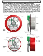
Page 21: ...ided and prevent accidental pulling of the station Two versions of the Manual Pull Station are available depending on the mounting configuration desired A flush mount option P N 24168 is recessed into the mounting wall and features a red cover plate See Figure 2 8a A surface mount option P N 24290 features a red cover cup See Figure 2 8b Both versions utilize an included octagonal outlet conduit b...

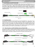
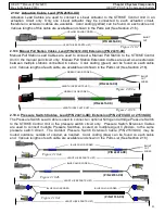
Page 22: ...bles are pre terminated with connectors and color coded to allow easy installation and troubleshooting These cables are divided into two groups lead cables and extension cables Lead cables feature blunt cut wires on one end for connection to the terminal strip TB1 on the STRIKE Control Unit and a connector on the opposite end that mates with an external device such as a detection device Manual Pul...

Page 23: ...R CODED BLUNT CUT WIRES P N 24413 XX LENGTH SEE PARTS LIST GREEN COLOR CODED Figure 2 10 3b LENGTH SEE PARTS LIST LENGTH SEE PARTS LIST BLUE COLOR CODED Figure 2 10 4c P N 21539 XX BLUE COLOR CODED Figure 2 10 2 LENGTH SEE PARTS LIST YELLOW COLOR CODED P N 26354 XX BLUNT CUT 2 10 3 Manual Pull Station Cables Lead P N 24412 XX Extension P N 24413 XX Manual Pull Station Lead Cables are used to conne...

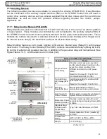
Page 24: ...See Figure 2 12b Specific battery replacement instructions and directions for installing this label are described in Section 5 5 The Replacement Batteries are UN DOT compliant for shipping purposes and must be stored in a clean cool 86ºF 30ºC max and dry environment Replacement battery shelf life is 10 years Figure 2 12b BATTERY IDENTIFICATION LABEL Figure 2 12a 2 10 5 Communication Cable P N 2526...

Page 25: ...SET BUTTON GAS VALVE A C POWER INDICATOR LED DOOR LOCKNUT P N 24695 2 13 Auxiliary Devices The following auxiliary devices are available for use with the Amerex STRIKE ECS Relay Modules can be connected to the auxiliary outputs terminal TB2 on the STRIKE Control Unit and used to control other auxiliary devices such as Amerex supplied Electric Gas Valves and Horn and Strobe Assemblies as well as ot...

Page 26: ...accessories are available for use with the Amerex STRIKE ECS when installing a Linear Heat Detector LHD as a detection device When installing an LHD in a PCU it must be secured using LHD Support Clips and Support Tubing or padded P Clamps These items may be attached using installer supplied fasteners or Amerex supplied rivet style or quick fasteners When penetrating a PCU wall with an LHD an LHD B...

Page 27: ...and lock washer Rivet Nuts P N 20536 qty 10 contain a female 1 4 20UN 2B thread by approx 3 4 19 05 mm depth Attach LHD support clips using a standard 1 4 20UN bolt and lock washer The Rivet Nut Installation Set P N 20552 contains a mandrel and nosepiece for installing either rivet studs or nuts Figure 2 14 3a P N 20535 Figure 2 14 3b P N 20536 Figure 2 14 4a Figure 2 14 2 2 14 4 LHD Bulkhead Quik...

Page 28: ...tection circuit in place of the actual LHD already installed and can be subjected to set point temperatures to verify that the STRIKE Control Unit responds properly These one time use devices can then be removed from the circuit and properly disposed LHD Test Leads are 12 long and supplied in bags of quantity 10 each All dimensions are in inches mm Figure 2 15 1 Figure 2 15 2 LED INDICATOR PUSH TO...

Page 29: ...9 50 Detection Lead Cable 50 Foot Length 24409 99 Detection Lead Cable 99 Foot Length 5 24410 03 Detection Extension Cable 3 Foot Length 24410 05 Detection Extension Cable 5 Foot Length 24410 10 Detection Extension Cable 10 Foot Length 6 26354 10 Actuation Lead Cable 10 Foot Length 26354 25 Actuation Lead Cable 25 Foot Length 26354 50 Actuation Lead Cable 50 Foot Length 26354 99 Actuation Lead Cab...

Page 30: ...terface Cable 14 23474 End of Line Module EOL 15 24903 Replacement Battery 16 24695 Relay Module Control 17 21396 Horn Strobe Assembly 18 23524 LHD Support Clips SS Bag of 25 19 24539 LHD Support Tubing Bag of 25 20 18720 Padded P Clamps Bag of 25 21 24832 Quick Fasteners Bag of 24 22 20535 Rivet Stud Hood Fastener Bag of 10 23 20536 Rivet Nut Hood Fastener Bag of 10 24 20552 Rivet Installation To...

Page 31: ...and cable lengths 3 2 Nozzles Each Nozzle P N 26330 is designed and tested to cover a maximum area of 2184 square inches 15 square feet with a maximum diagonal dimension of 67 inches See Figure 3 2a A nozzle or nozzles must be placed upstream of each filter module in the PCU See Figure 3 2c It is not required to place a nozzle downstream of the last filter bank however if an extra nozzle is availa...

Page 32: ...the quantity of Nozzles required to protect the hazard s Table 3 3 shows the appropriate quantity of Nozzles to be selected for each Agent Cylinder The quantity of Nozzles per Agent Cylinder must not be exceeded Model Part Number Max Quantity of Nozzles HX25ABC PRS SW 26318 2 HX50ABC PRS SW 26320 4 Table 3 3 DETECTION NETWORK LHD AGENT DISTRIBUTION NETWORK Figure 3 2d AIR FLOW NOZZLES FILTER BANKS...

Page 33: ...e selection and not to exceed those temperature ratings during normal equipment operation When installing the Agent Distribution Network the installer must comply with the hose manufacturer s minimum hose bend radius requirements Avoid pinch points or possible chafing of the network The number of Nozzles used in the Agent Distribution Network must match what is specified in Table 3 3 for the Agent...

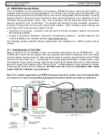
Page 34: ...e However this ratio must be observed for the minimum versus maximum hose length Example If the longest 1 2 inch I D hose leading from where the network splits T1 to Nozzle is 15 feet the shortest 1 2 inch I D hose leading from the same network split location cannot be less than 5 feet and all 1 2 inch I D hoses together must fall within the length specified 3 4 1 HX25 Agent Distribution Network 2...

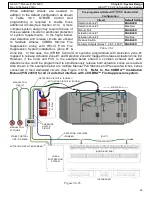
Page 35: ... However this ratio must be observed for the minimum versus maximum hose length Example If the longest 1 2 inch I D hose leading from where the network splits T1 to T2 is 15 feet the shortest 1 2 inch I D hose leading from the same network split location cannot be less than 5 feet and all 1 2 inch I D hoses together must fall within the length specified 3 4 I D HOSE 1 2 ELBOW OPTIONAL 1 2 I D 1 2 ...

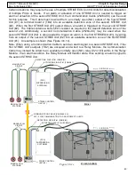
Page 36: ...butor 3 4 19 1 45 13 7 5 1 5 2 0 Distributor to each Nozzle 1 2 12 7 15 4 6 2 0 Cylinder to any 60 18 3 5 1 5 All 1 2 hose 60 18 3 All 3 4 hose 45 13 7 5 1 5 Table 3 4 3 Note Hose length may be unbalanced in a maximum ratio of 3 1 where the Agent Distribution Network splits Distributor to Nozzle However this ratio must be observed for the minimum versus maximum hose length Example If the longest 1...

Page 37: ...r application the total hose length in the network must not exceed 100 ft 30 4 meters A Vent Check P N 10173 R is installed in only the last Control Head in the network The Amerex HELIX Fire Suppression System has two different options available for system actuation including the Electric Control Head and the Pneumatic Control Head The following section explains how to design each of the options C...

Page 38: ...ntrol Head must not exceed 100 ft 30 4 meters The installer must avoid routing any component related to the Pneumatic Actuation Network through hazard areas The installer must comply with minimum hose bend radius requirements Avoid pinch points or possible chafing of Pneumatic Actuation Network The Pneumatic Actuation Network must be secured to a structure at a maximum of 24 intervals with the use...

Page 39: ...maximum of 8 eight cylinders may be used in a single system Each control head will be connected in a series Figure 3 5 2a or parallel Figure 3 5 2b arrangement to the Pneumatic Actuation Network Parallel arrangements will be connected using a 1 4 NPT tee The last control head in each leg of the circuit will contain the Vent Check s P N 10173 R PRESSURE SWITCH P N 22573 R or 23850 R LINEAR ACT P N ...

Page 40: ... biz The following sections describe design requirements and limitations for a HELIX system and its circuits 3 6 1 Introduction to STRIKE ECS Refer to Section 2 7 for available circuits and features associated with the STRIKE ECS The STRIKE ECS Control Unit is supplied with a pre programmed default configuration with only certain circuits enabled requiring that only those circuits be used in a sys...

Page 41: ...d and PCU in the example below shared a common exhaust duct each detection zone could be programmed to simultaneously release both actuation zones as required Also shown in the example below are multiple Manual Pull Stations and Pressure Switches series connected in their dedicated circuits See Figure 3 6 1b Refer to the COBRA Installation Manual P N 23853 for all circuits that interface with a CO...

Page 42: ...econd STRIKE Unit 2 is also needed to trigger an alarm in the first STRIKEUnit 1 by wiring from an output of the second STRIKE Unit 2 into an available detection zone of the first STRIKE Unit 1 An example is shown See Figure 3 6 1c Note When using a Communication Cable to send an alarm signal to a second STRIKE Unit if the first STRIKE Unit s outputs TB2 are occupied and wired to a Relay Module th...

Page 43: ...l multiple STRIKE Units additional Communication Cables P N 25264 XX are required for each STRIKE Unit An example is shown See Figure 3 6 1d A Communication Cable P N 25264 XX may also be used to trigger an alarm actuation of a STRIKE Unit from a snap action switch located in a hood suppression system This Cable must be wired from a normally open NO closed in alarm output of the snap action switch...

Page 44: ...ch STRIKE Unit Linear Heat Detectors LHD are preset 356ºF 180ºC heat sensing devices capable of sensing an overheat condition at any point along its routed path Features and limitations for LHDs are Preset device with 356ºF 180ºC set point Maximum ambient operating temperature 250ºF 121ºC One time use device and must be replaced after sensing an overheat condition Flexible 2 5 64 mm min bend radiu...

Page 45: ...LHD Support Clips P N 23524 Split Tubing P N 24539 or P Clamps P N 18720 R must be used for support at a minimum of every 24 0 61 m This method provides detection for up to 3 consecutive filter banks within the PCU Larger PCUs utilizing more than 3 consecutive filter banks must have an additional S shaped route positioned upstream which can be accomplished using a single LHD routed through the PCU...

Page 46: ...onnection See Figure 3 6 3d 3 4 electrical knockouts are provided on the STRIKE Unit All installations must follow NFPA 70 National Electric Code and all state and local codes Each actuation circuit is limited to 100 feet 30 5 m A Linear Actuator P N 20500 R is always installed at the end of each circuit A example of an actuation circuit is shown below See Figure 3 6 3 If the second actuation circ...

Page 47: ... of egress Consult the local AHJ for final approval for quantity locations mounting heights and all other considerations prior to installing all Manual Pull Stations An example of a single Manual Pull Station installed in the dedicated manual pull circuit is shown below See Figure 3 6 4a An example of the same circuit with multiple Manual Pull Stations connected in series is also shown See Figure ...

Page 48: ...ion Cables must be routed through approved outdoor electrical conduit as protection See Figure 3 6 3c Outdoor installations using an Electric Nitrogen Actuator and Pneumatic Control Heads must use a 3 4 outdoor junction box located above each control head to house the Lead Extension Cable ends and connections See Figure 3 6 5c Alternately the Outdoor Pressure Switch Extension Cable P N 21539 XX ma...

Page 49: ... down of electric fans cooking equipment or Electric Gas Valves All PCUs that use Class A combustible filter media require PCU fan shutdown upon actuation If an auxiliary FACP is used it can be connected to and receive a supervised signal from the STRIKE Control Unit in the event of a fault or alarm condition The STRIKE Control Unit also provides terminal connections for an EOL resistor as require...

Page 50: ...me should the Agent Cylinder be utilized with more than the appropriate quantity of Nozzles as depicted in Table 3 3 Installation Requirements Do not locate Cylinder Brackets in hazard areas where heat or fire can damage the Agent Cylinder Do not locate Cylinder Brackets in areas where risk of damage can occur to the Agent Cylinder or Cylinder Bracket Mount the Agent Cylinder in a location that on...

Page 51: ...f the equipment 4 2 3 Nozzle Placement Mounting Nozzles must be aimed with 45 fittings Use PTFE thread tape for all connections Each defined filter bank or hazard must have a minimum of one nozzle for protection If a hazard is too large for one nozzle the hazard must be divided into sections with a nozzle protecting each section Carefully aim multiple nozzles at the hazard area to ensure coverage ...

Page 52: ... place Install Linear Actuator P N 20500 R and tighten hand tight Do not over tighten Do not use PTFE thread tape Ensure Linear Actuator body makes full contact with control head The Linear Actuator will be connected to the STRIKE ECS See Section 4 8 2 6 For indoor applications or when Agent Cylinders are within an enclosure secure Linear Actuator lead to the Agent Cylinder Valve body with a cable...

Page 53: ... ft lbs 5 Install 1 4 NPT Pneumatic Actuation Network See Section 3 5 2 Use PTFE thread tape Tighten a minimum of two turns past hand tight 6 Install Vent Check P N 10173 R For multiple Control Heads each Control Head is installed in series See Figure 4 3 2b and a Vent Check is required at the last Control Head See Figure 4 3 2a Use PTFE thread tape Tighten a minimum of two turns past hand tight 7...

Page 54: ...ibility The Indoor Actuator Bracket See Figure 4 5 can be secured to a mounting surface in 2 ways Qty 4 for Indoor Bracket 1 4 SAE Grade 8 bolts and Nylock locking nuts installed in through holes in mounting surface Qty 4 for Indoor Bracket 1 4 SAE Grade 8 bolts installed with locking washers into blind tapped holes in mounting surface To Install Electric Nitrogen Actuator P N 20775 R 1 Install 2 ...

Page 55: ...UNTING SCREWS P N 10573 TAMPER SEAL P N 01387 4 6 Pneumatic Actuation Network Installation Following installation of any Pneumatic Control Heads and Electric Nitrogen Actuators install the Pneumatic Actuation Network using the guidelines defined in Section 3 5 2 After the Pneumatic Actuation Network is complete and assembled test the network per instructions in Section 6 2 8 for functionality ACTU...

Page 56: ...al Pull Stations must be located and installed See Section 4 7 8 All Pressure Switches used in a suppression system must be located Any optional devices including Relay Modules and the supported devices such as external alarms fans motors etc must be located and installed See Section 4 7 9 Appropriate wiring paths must be established and wiring installed including any required protective conduit f...

Page 57: ... in Figure 4 7 2a 2 Use the dimensions shown in Figure 2 7 1b or use the enclosure as a template to mark then drill the top two holes in the selected mounting surface 3 Loosely assemble the enclosure to the mounting surface using appropriate hardware 10 fasteners are recommended Level the enclosure and match drill the remaining two lower holes 4 Finish the installation by securely attaching the en...

Page 58: ...ng in 3 horizontal runs across the cross sectional area of the PCU See Figure 4 7 3 The LHD wire must NOT be installed within any hazard area that exceeds 250 F 121ºC during normal operating conditions Physical contact with any high heat surfaces exceeding 250 F 121ºC is not permitted The LHD must NOT be obscured by supports or support structures and should be fully exposed to air passing through ...

Page 59: ...PATTERN BEHIND LAST FILTER BANK DOWNSTREAM AMBIENT AIR TEMPERATURE 250ºF 121ºC MAX P CLAMPS P N 18720 OR LHD CLIPS P N 23524 LHD TUBING P N 24744 XX FASTENERS P N 24832 20535 20536 24 609 6 MAX SPACING BETWEEN SUPPORTS AIR FLOW PCU P CLAMP P N 18720 R SUPPORT CLIP P N 23254 SUPPORT TUBING P N 24539 PCU STRUCTURE PCU STRUCTURE LHD EXPOSED TO PASSING AIR LHD EXPOSED TO PASSING AIR INDOOR INSTALLATIO...

Page 60: ... 24737 or Compression Seal P N 26427 Installation Any LHD penetration through the bulkhead or wall of a PCU requires the use of an LHD Quik Seal or Compression Seal LHDs are supplied with an uninstalled male connector on the downstream side opposite end from STRIKE Control Unit to facilitate installation through any LHD Quik Seals All LHD Quik Seals must be installed with LHD routed through each p...

Page 61: ...INTERNAL FIBER SEAL Figure 4 7 5b 2 TIGHTEN COMPRESSION NUT UNTIL FULLY BOTTOMED Figure 4 7 5c 1 FULLY INSTALL LHD PER SECTION 4 7 3 BULKHEAD LOCK WASHER SEALING WASHER BODY 1 1 8 29 mm HOLE Figure 4 7 5d JAM NUT LHD P N 24744 XX UNINSTALLED MALE CONNECTOR END OF LHD COMPRESSION NUT LOOSENED INTERNAL FIBER SEAL Figure 4 7 5e 2 TIGHTEN COMPRESSION NUT UNTIL FULLY BOTTOMED Figure 4 7 5f COMPR SEAL P...

Page 62: ...Actuator Installation Refer to section 4 3 for installation of the Linear Actuator P N 20500 R into the Electric Control Head P N 14032 R Refer to section 4 5 for installation of the Linear Actuator P N 20500 R into the Electric Nitrogen Actuator P N 20775 R 4 7 8 Manual Pull Station Installation The Amerex STRIKE ECS requires at least one Manual Pull Station P N 24168 or 24290 be installed Manual...

Page 63: ...ions See Figure 4 7 8a 1 Use the box as a template to match drill two holes in the selected mounting surface with a stud or solid structure 2 Assemble the electrical box to the mounting surface and stud using appropriate hardware 3 The Manual Pull Station is attached to the electrical box using the 2 provided 8 screws Install the provided plastic plugs 2 in the remaining two holes on the cover Do ...

Page 64: ...7 8b 1 If walls are installed use the box as a template to cut out a hole in the mounting surface or wall directly adjacent to a stud 2 Drill two mounting holes approx Ø 5 32 in the side of the box that will attach to the stud 3 Mount the box to the stud using appropriate hardware so that the front edge of the box is flush with the mounting surface 4 The Manual Pull Station is attached to the elec...

Page 65: ...considered when choosing an appropriate location Any obstacles moving parts hazard areas or bulkheads that may inhibit complete connection of all system components or cause damage to components must be avoided Relay Modules must be mounted in a dry environment protected from outside environmental conditions or possible damage and must be mounted to a surface capable of supporting the weight of the...

Page 66: ...ices such as Relay Modules FACPs gas valves and external alarms signaling devices require installer supplied wiring Always contact the local AHJ for a proposed wiring installation All installations must follow NFPA 70 National Electric Code and all state and local codes Traditional wiring support methods or EMT conduit may be used as required The following subsections describe the available cables...

Page 67: ...ion Reference Figure 4 8 1b for specific instructions for cable connection at the Manual Pull Station For single detection device LHD circuit installations See Figure 4 8 1a 1 Route the blunt cut end of the Detection Lead Cable P N 24409 XX from the installed LHD back into the STRIKE Control Unit enclosure through the selected knockout Any excess length in the cable should be pulled into the STRIK...

Page 68: ...cable connector F For outdoor installations this connection should be housed in an outdoor junction box 4 Route the blunt cut end of the Manual Pull Lead Cable P N 24412 XX from the installed electrical box back to the STRIKE Control Unit enclosure until only about 5 of the electrical connector remains in the electrical box as shown Any excess length in the cable should be pulled to the Control Un...

Page 69: ...rcuit For actuation circuit installations See Figure 4 8 2 1 Beginning at the installed Linear Actuator on top of the Electric Control Head or Electric Nitrogen Actuator route the blunt cut end of the Actuation Lead Cable P N 24411 XX from the junction box if required to and into the STRIKE Control Unit enclosure through the selected knockout The entire route must be within electrical conduit for ...

Page 70: ... remains in the electrical box as shown Any excess length in the cable should be pulled into the Control Unit enclosure Do not cut pinch crush or chafe any electrical wiring or connectors during installation 2 Connect the female Pull Station connector F to the lead cable connector M 3 Install an EOL Module P N 23474 on the male Manual Pull Station connector M 4 Tuck the electrical connections into...

Page 71: ...first Manual Pull Station location closest to the STRIKE Control Unit route the blunt cut end of the Manual Pull Lead Cable P N 24412 XX from the installed electrical box back to the STRIKE Control Unit enclosure until only about 5 127 0 of the electrical connector remains in the electrical box as shown Any excess length in the cable should be pulled to the Control Unit enclosure See Figure 4 9 3a...

Page 72: ...rcuit installations See Figure 4 8 4a 1 Beginning at the installed Pressure Switch on the Agent Cylinder route the blunt cut end of the Pressure Switch Lead Cable P N 24414 XX from the Agent Cylinder or junction box if required See Section 3 6 5 to the inside of the STRIKE Control Unit enclosure through the selected knockout Any excess length in the cable should be pulled into the STRIKE Control U...

Page 73: ...ure through the selected knockout This circuit may be routed through the same conduit as the actuation circuit if used Any excess length in the cable should be pulled into the STRIKE Control Unit enclosure Do not cut pinch crush or chafe any electrical wiring or connectors during installation 4 At the last Pressure Switch connect the Pressure Switch connectors to the extension cable connectors M t...

Page 74: ...ions See Figure 4 8 5a Electric Gas Valve Wiring Relay 1 1 Verify the voltage and current rating of the installed Electric Gas Valve device is 120 240 VAC and less than 10 amps 2 Route and connect the Line and Neutral gas valve leads to position 3 and 4 of the lower black terminal strip using 12 22 AWG wiring Torque terminal screws to 7 in lbs Connect ground wiring to the provided lug 3 Route and ...

Page 75: ...WG RELAY 2 WIRING If an Auxiliary FACP is used the STRIKE Control Unit features additional alarm and fault outputs for connection to an auxiliary fire alarm control panel FACP An EOL may also be installed on the STRIKE Control Unit Connect and route wiring from the FACP to and into the STRIKE Control Unit enclosure using 16 24 AWG wiring See Figure 4 8 5b Termination of wiring to the STRIKE Contro...

Page 76: ... each cable is fully installed and properly secured prior to trimming Since trimming will remove the installed color coded P N label on the cable end each cable is supplied with an extra color coded label which can be installed on the trimmed cable end for circuit color code and part number reference Terminate all installed cables where shown in Figure Table 4 9b A Field Wiring Diagram label is al...

Page 77: ... If a Pressure Switch is NOT used leave this jumper wire installed The Communication Cable P N 25264 XX may be used on an available Detection Zone to receive an alarm signal from an additional STRIKE Unit external FACP or alarm initiating snap action switch See Figures 3 6 1c d e TERMINAL BOARD 2 TB2 TERMINATE ALL INSTALLER SUPPLIED WIRING WHERE SHOWN IN TABLE 4 9b LEAVE SCREW TERMINALS EMPTY FOR ...

Page 78: ...When the device contacts are closed an alarm condition will be initiated in the Strike Unit through Detection Zone 2 Strike Unit programming is required to enable Detection Zone 2 and map that zone to the appropriate Actuation Zone Note Cables connected to the STRIKE Unit on Terminal Board 1 TB1 are limited to only Amerex supplied cables as permitted in this manual Any wiring or circuits connected...

Page 79: ... functions so that power is not drained from the included service batteries This temporary battery must also be used during function testing and initial commissioning See Section 4 11 Also programming functions require use of the PC Interface Cable P N 16609 and a laptop or tablet with the latest Amerex STRIKE PC software installed The latest version of PC software is available on and can be downl...

Page 80: ... in the Users Programs or Program Files folder in a sub folder named Amerex The software also creates a folder in the users Documents folder named My Amerex Files In the My Amerex Files folder a STRIKE ECS Unit folder is created with subfolders including Config EventLog and Update After installation is complete an Amerex STRIKE ECS Utility executable icon is placed on the user s Desktop Next conne...

Page 81: ...internal clock by selecting the File tab and Set Clock Enter the password in the password prompt after which a Clock window will appear Enter the desired date and time or check Use current date and time PC time and click the Set System Time box Verify the system time is correct by clicking the Get System Time box See Figure 4 10 3b Downloading A System Configuration Prior to making any changes to ...

Page 82: ...l Enabled Discharge Zones Only Discharge Zone 1 Y Enabled Only Not Shown on Utility Window Enabled Only Discharge Zone 2 Y Enabled Disabled Default Enabled Disabled Pressure Switch Y Enabled Default Disabled Enabled Disabled Alarm Fault Outputs Y Each Enabled Default Disabled Each Enabled Disabled Delays 0 30 seconds FACP Alarm 5 30 seconds FACP Fault 0 30 seconds Relay 1 2 3 0 second delay Only F...

Page 83: ...ystem Output Programming The various available outputs may be used in conjunction with a Relay Module to alert or switch external devices on or off in the event of an overheat fire or trouble condition These outputs are all enabled as a default setting but may be disabled if unused by unchecking the Enable box next to each Each output circuit may be programmed with an optional delay from 0 30 seco...

Page 84: ...matically exit programming mode and return to normal condition after 3 minutes if no programming functions are performed as indicated by a single LED flash and audible alarm beep Re enter programming mode in the same manner as described earlier in this section Once uploaded the STRIKE ECS is now configured as shown in the STRIKE ECS Unit Utility window The STRIKE Control Unit will exit programming...

Page 85: ...status The Monitor Mode window now displays the status of all available circuits as indicated by a colored circle next to each item Displayed colors represent the following for detection and discharge zones Green Working Enabled Circuit Gray Disabled Circuit Yellow Fault Condition Exists on Circuit Red Alarm Condition Exists on Circuit Primary and secondary battery voltages are displayed including...

Page 86: ...sumption or an unwanted discharge of the Amerex HELIX Fire Suppression System A Fire Alarm Module P N 23651 must be installed in place of each Linear Actuator on the actuation circuits These resettable modules simulate an actual Linear Actuator and visually indicate a fully functioning actuation circuit during testing See Figure 4 11 A fault condition will occur temporarily on the STRIKE Control U...

Page 87: ...ve the used LHD Test Lead and reconnect the original circuit After verifying the LHD and associated actuation zone s are functioning properly allow the LHD Test Lead to cool and remove from the circuit Reset the STRIKE Control Unit per the following instructions 1 The audible alarm can be silenced by pressing the Alarm Silence button 2 Press the Push To Reset button on each Alarm Module P N 23651 ...

Page 88: ...einstall the pull pin through the assembly Install the included extra green Tamper Seal to secure the pull pin in place See Figure 4 11 3c To reset the STRIKE Control Unit perform the same reset procedure shown previously for SHDs Repeat this test process for all Manual Pull Stations used in the Amerex STRIKE ECS Figure 4 11 3b 1 LIFT AND REMOVE PULL PIN BREAK TAMPER SEAL IF INSTALLED 2 PULL RING ...

Page 89: ...from the STRIKE Control Unit Verify the following results have occurred on the STRIKE Control Unit See Table 4 11 4b Reconnect the battery and verify the STRIKE Control Unit returns to normal condition with the green System Normal LED flashing once every 4 seconds Indicator Result After Circuit Disconnect Green System Normal LED OFF Yellow Battery Fault LED FLASHES every 4 seconds after approximat...

Page 90: ...RIKE Control Unit in the following order Disconnect the secondary battery first then disconnect the temporary spare Replacement Battery from the Primary location The STRIKE Control Unit will turn off completely 4 Locate the original two batteries included with the STRIKE Control Unit Verify each is installed in the provided battery brackets in the STRIKE Control Unit enclosure First connect the le...

Page 91: ...r This review should include Disclose all system components and functionality of each component Disclose all hazard high risk areas and emphasize the necessity of good house keeping measures for those areas Explain how the system can activate automatically if automatic detection is used and how to use any manual actuation stations If the system is connected through a relay that powers the unit dow...

Page 92: ...s or clutter Verify the green tamper seal is installed on each device Verify that the maintenance tag or certificate is in place and up to date Record the date of inspection and initials of inspector Verify the physical condition of all components Inspect for damage or conditions that may prevent operation Inspect the Agent Cylinder Pressure Gauge s The yellow pointer on the Agent Cylinder Pressur...

Page 93: ...protective Dust Caps P N 10167 If protective Dust Caps are missing from Nozzles re install new ones Purge the Agent Distribution Network with air or nitrogen only See Section 6 2 2 If a Pneumatic Actuation Network is used unscrew Nitrogen Cylinders from actuators Cycle each actuator several times verifying free travel of Puncture Stem Assembly inside each actuator If any defects are found rebuild ...

Page 94: ...ving the current Primary battery and replacing it with the current Secondary battery and a new Replacement Battery P N 24903 is installed at the Secondary location Before performing this replacement procedure or performing system maintenance follow the procedure for servicing the system The battery replacement procedure shall also be performed following these events Primary Battery is over 6 month...

Page 95: ...T PREVIOUS SECONDARY BATTERY TO Primary LOCATION NEW PRIMARY BATTERY 6 POPULATE NEW BATTERY REPLACEMENT LABEL AND APPLY OVER OLD LABEL 1 DISCONNECT SECONDARY BATTERY FIRST 2 DISCONNECT AND REMOVE PRIMARY BATTERY PREVIOUS PRIMARY BATTERY PREVIOUS SECONDARY BATTERY PREVIOUS SECONDARY BATTERY 3 MOVE PREVIOUS SECONDARY BATTERY TO PRIMARY LOCATION LEFT PREVIOUS SECONDARY BATTERY NEW REPLACEMENT BATTERY...

Page 96: ...10 FITTING TEE HANDLE P N 10134 Chapter 6 Recharge 6 1 Service Recharge Tools Only genuine Amerex service recharge tools should be used for servicing Amerex HELIX Fire Suppression System Proper protective equipment must be used safety glasses steel toe shoes hard hats etc when servicing or recharging the Amerex HELIX Fire Suppression System 6 1 1 Recharge Adapter P N 10136 The Recharge Adapter is ...

Page 97: ...rom McMaster Carr or other hardware supply stores The Pump Wrench should be less than 0 30 7 62 mm in thickness for proper fit on the Agent Cylinder Valve TEE HANDLE P N 10134 AGENT CYLINDER VALVE Figure 6 1 4 AGENT CYLINDER VALVE PUMP WRENCH Figure 6 1 5 HANSEN 10 FITTING Figure 6 1 6 6 1 6 Pneumatic Actuation Network Test Adapter P N 10895 The Actuation Network Test Adapter is used in place of a...

Page 98: ...rfaces Note Amerex Dry Chemical Agent is considered a nuisance dust and is non toxic See SDS on Amerex website at www amerex fire com 3 Additionally power spraying or steam cleaning can be done to remove any additional Dry Chemical Agent Mild soapy water can sometimes be utilized Contact equipment owner operator for permission to use water prior to taking this step 6 2 1 Agent Cylinder Control Hea...

Page 99: ... loaded and can be forced in and out of the piston shaft Note Do not remove Spring Plunger from Piston If this part is compromised replace the entire Pneumatic Piston Assembly P N 17635 Control Head Reassembly See Figure 6 2 1a 4 3 2a 11 Lubrication O Ring P N 10148 must be lightly lubricated with Visilox P N L0172 or equivalent silicone style lubricant Inner bore of the Control Head Body P N 1166...

Page 100: ...amage has occurred replace the component Stainless steel disc punched from spent Linear Actuator P N 20500 R must always be removed in the event of an automatic actuation Control Head Reassembly See Figure 6 2 1b 8 Place Retaining Ring P N 14037 into Base P N 14034 followed by the Piston P N 14035 in orientation shown 9 Before adding any thread lock screw the Body P N 26426 into the Base and test ...

Page 101: ...bstructions or replace the section of the Agent Distribution Network 4 Reinstall all Protective Nozzle Blow Off Caps P N 10167 6 2 3 Agent Cylinder Removal 1 Disconnect the Pressure Switch from the Agent Cylinder Valve See Figures 4 8 4a and 4 8 4b Do not attempt to remove Low Pressure Switch from Agent Cylinder Valve 2 Ensure Shipping and Anti Recoil Plates are installed on Agent Cylinder Valve S...

Page 102: ...asher P N 10102 Replace any damaged components 9 Remove and discard Valve Stem Replace with a new Valve Stem P N 10095 10 Clean and rinse entire Agent Cylinder Valve with water and dry all parts 11 Inspect all external components of the Agent Cylinder Valve including the Pressure Gauge P N 08714 Gauge Guard P N 08680 Pressure Switch P N 17609 and Rupture Disc P N 25646 See Figure 6 2 4b If any com...

Page 103: ... COULD RESULT IN ADVERSE SYSTEM PERFORMANCE PROPERTY DAMAGE SERIOUS BODILY INJURY AND POSSIBLE DEATH CONSULT THE SAFETY DATA SHEET SDS FOUND ON AMEREX WEBSITE WWW AMEREX FIRE COM FOR THE PARTICULAR AGENT BEING USED After completely emptying and vacuuming the Agent Cylinder See Section 6 2 4 fill the Agent Cylinder with the appropriate volume of Dry Chemical Agent See Table 2 1 1 Fill only with amo...

Page 104: ...r P N 20458 with O ring P N 10513 from the top of the Actuator Body P N 20774 7 Remove the Puncture Stem Assembly P N 22873 with O ring P N 09989 and 2 back up Rings P N 09993 from the Actuator Body P N 20774 Remove Spring P N 10097 and Gasket P N 07247 Actuator Cleaning See Figure 6 2 7 8 Inspect and clean the inner bore of Actuator Body P N 20774 If any scarring or damage has occurred to inner b...

Page 105: ...h control head actuates Pistons equipped with a Locking Plunger should lock in the open or actuated position 5 Verify that each component and connection in the Pneumatic Actuation Network has no leaks 6 To relieve pressure in the Pneumatic Actuation Network unseat the Vent Check s P N 10173 R on the control head s After all pressure is relieved reinstall Vent Check 7 Reset all control head pistons...

Page 106: ...dirt grease and foreign material use mild soap and water for cleaning process no harsh solvents Verify that the nameplate for each Nitrogen Cylinder is in place and fully legible Inspect the Nitrogen Cylinders for corrosion abrasion or dents Relieve any pressure and discard if integrity of the Nitrogen Cylinder has been compromised 3 Remove old Rupture Disc P N 09958 and discard by fully screwing ...

Page 107: ...es the NOMINAL PRESSURE line Draw a second line horizontally from the point of intersection to the CYLINDER CHARGE PRESSURE vertical axis of the graph Increase the pressure from the regulated nitrogen supply to match the value read from the CYLINDER CHARGE PRESSURE axis Note Nitrogen used for pressurizing must be dry with a dew point of 70 F 57 C or lower 4 Inspect sealing seat on Nitrogen Cylinde...

Page 108: ...in the supply line Remove Nitrogen Cylinder P N 09956 R from the Recharge Adapter P N 10270 9 Check for leaks by applying leak detect fluid or soapy water to the Rupture Disc P N 09958 the Nitrogen Cylinder hex fitting threads and the Nitrogen Cylinder pressure gauge threads Look for bubbles in the leak detect fluid Bubbles may take several minutes to appear Dry any leak detect fluid from all surf...

Page 109: ...he Monitor Mode See Section 4 10 4 or Event Log See Section 7 5 can be used to identify the cause of an alarm Any one time use or damaged components must be replaced If an alarm condition actuated any discharge zones replace fired Linear Actuators P N 20500 R Reset the STRIKE Control Unit by pressing and holding the System Reset button for approximately 10 seconds and verify the STRIKE Control Uni...

Page 110: ...amaged the circuit may open resulting in a trouble condition Inspect the circuit for disconnected connectors broken or cut wiring or damaged components Another method for identifying damaged or faulty segments of the pressure switch circuit is to disconnect the two pressure switch connectors of the Pressure Switch Lead Cable and connect them together to each other closing the circuit If the troubl...

Page 111: ...nt Stand by with portable fire extinguisher and watch for sources of re ignition 7 5 Event Log The Event Log allows the user or servicing distributor to access a history of events that have occurred on Amerex STRIKE ECS The Event Log can be used to identify intermittent issues that may not always be seen by the servicing technician It may be used to determine the most recent maintenance performed ...

Page 112: ...ve button in the lower right of the window See Figure 7 5 The default folder is My Amerex Files STRIKE ECS Unit EventLog The file format is csv which can be opened and viewed using Microsoft Excel It is recommended that the title of the saved file include the location identification number and date SELECT TO VIEW EVENTS SELECT Event Log TAB Figure 7 5 CLICK TO SAVE EVENT LOG ...

Reviews: