40
HELIX™ Manual
(P/N 26291)
Chapter 3: System Design
Rev A (February 2018)
HELIX™ PCU
Fire Suppression System
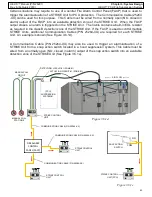
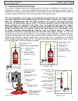
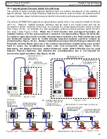
Certain situations may require the use of multiple STRIKE ECS Control Units for detection/actuation
of multiple PCUs or hoods. If an alarm or actuation of one STRIKE Unit is needed to trigger an
alarm or actuation of the second STRIKE Unit, the Communication Cable (25264
-
XX) can be used
for this purpose. This Cable must be wired from a normally open (NO) output of the first STRIKE
Unit (#1) on terminal board 2 (TB2) into an available detection zone of the second STRIKE Unit
(#2). When the first STRIKE Unit (#1) output closes, an alarm is triggered on the second STRIKE
Unit (#2). The Cable contains a built
-
in EOL resistor as required in the class B detection zone of the
second unit. Additionally, a second Communication Cable (25264
-
XX) may be used when the
second STRIKE
Unit (#2) is also needed to trigger an alarm in the first STRIKE
Unit (#1), by wiring
from an output of the second STRIKE
Unit (#2) into an available detection zone of the first STRIKE
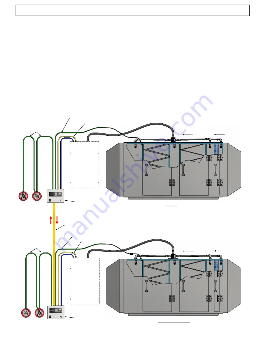
Unit (#1). An example is shown (See Figure 3.6.1c).
Note: When using a Communication Cable to send an alarm signal to a second STRIKE Unit, if the
first STRIKE Unit’s outputs (TB2) are occupied and wired to a Relay Module, the Communication
Cable may instead be wired to an available normally open (NO) relay (#2 or #3) within in the Relay
Module. In an alarm condition, the Relay Module will transfer state, thus sending an alarm signal to
the second STRIKE Unit.
MANUAL PULL
STATIONS
MANUAL PULL
CIRCUIT
AIR FLOW
ACTUATION CIRCUIT #1 (ZONE #1)
DETECTION CIRCUIT #1 (ZONE #1)
STRIKE CONTROL
UNIT (#2)
(PCU)
SUPPRESSION
SYSTEM #2
COMMUNICATION CABLE (P/N 25264
-
XX);
QTY: 2 FOR COMMUNICATION TO AND FROM BOTH UNITS
Figure 3.6.1c
PCU #2 (OR HOOD)
DETECTION CIRCUIT #1 (ZONE #1)
MANUAL PULL
STATIONS
MANUAL PULL
CIRCUIT
AIR FLOW
ACTUATION CIRCUIT #1 (ZONE #1)
STRIKE CONTROL
UNIT (#1)
(PCU)
SUPPRESSION
SYSTEM #1
PCU #1

