47
HELIX™ Manual
(P/N 26291)
Chapter 3: System Design
Rev A (February 2018)
HELIX™ PCU
Fire Suppression System
3.6.6 Relay Module & Auxiliary Circuit Design
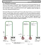
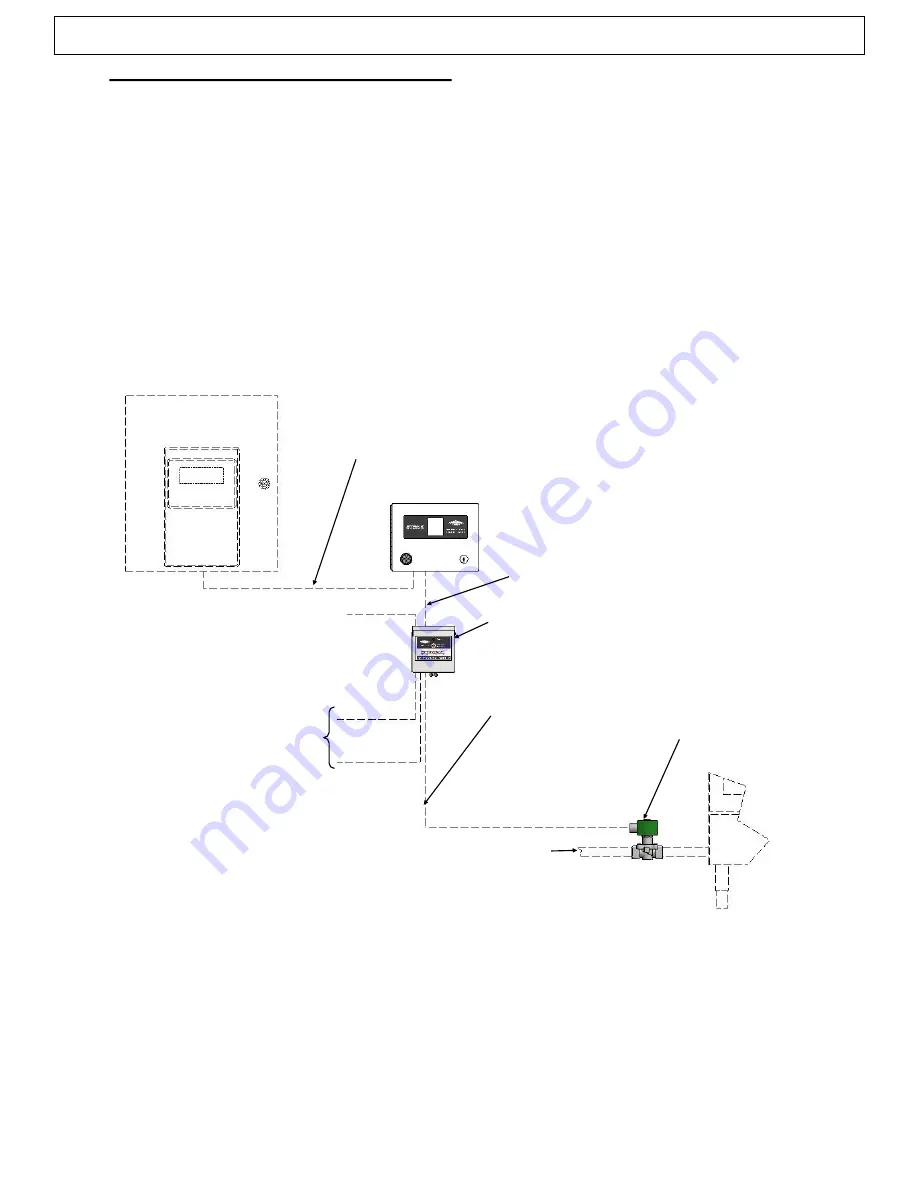
The Amerex STRIKE ECS supports the use of an optional Relay Module to control A/C power to
external devices and supports communication with an optional auxiliary Fire Alarm Control Panel
(FACP). These circuits utilize installer supplied wiring and connect to a terminal board (TB2)
located on the STRIKE Control Unit. The Relay Control Module (P/N 24695) features a manually
resettable gas valve relay with two additional relays (Relay #2 & #3) for controlling power to other
optional devices such as PCU fans, alarms, appliances, motors, pumps, etc.
Note:
A qualified
electrician must perform any field wiring and connections involving the shut
-
down of electric
fans, cooking equipment or Electric Gas Valves. All PCUs that use Class A combustible filter
media require PCU fan shutdown upon actuation.
If an auxiliary FACP is used, it can be connected to, and receive a supervised signal from the
STRIKE Control Unit in the event of a fault or alarm condition. The STRIKE Control Unit also
provides terminal connections for an EOL resistor as required in the FACP circuit. An example of a
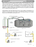
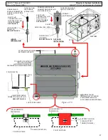
circuit design utilizing a Relay Module and auxiliary FACP is shown (See Figure 3.6.6).
STRIKE CONTROL
UNIT (P/N 23826
)
GAS SUPPLY
(FACP)
(APPLIANCE)
RELAY MODULE
(P/N 24695)
ELECTRIC GAS VALVE
(P/N VARIES)
A/C POWER IN
(INSTALLER SUPPLIED WIRING)
RELAY #2 & #3
A/C POWER CIRCUITS
FOR CONTROL
OF PCU FAN, MOTOR,
PUMP, APPLIANCE, SNAP ACTION
SWITCHES,
ETC.
(INSTALLER SUPPLIED)
FACP SUPERVISED CIRCUIT
(INSTALLER SUPPLIED WIRING)
RELAY CONTROL CIRCUIT
(INSTALLER SUPPLIED WIRING)
RELAY #1, MANUALLY
RESETTABLE GAS VALVE
CIRCUIT (NC)
(INSTALLER SUPPLIED
WIRING)
Figure 3.6.6


