48
HELIX™ Manual
(P/N 26291)
Chapter 4: System Installation
Rev A (February 2018)
HELIX™ PCU
Fire Suppression System
Chapter 4: System Installation
This Chapter describes installation of the Amerex HELIX Fire Suppression System. Prior to system
installation, a complete PCU analysis must be performed and a proposed system layout or
schematic, including a bill of
materials, shall be created per Chapter 3. Always contact the local
AHJ for fire codes and health inspectors for special requirements associated with any proposed
installation. All installations are to be in accordance with NFPA 17, NFPA 72 (National Fire Alarm
Code) and NFPA 70 (National Electric Code) and all other state and local codes.
4.1 Agent Cylinder & Agent Cylinder Bracket Selection
Agent Cylinders and their associated Cylinder Brackets can be selected after first determining the
quantity of Nozzles required to protect the hazard(s). Table 3.3 shows the appropriate quantity of
Nozzles to be selected for any Agent Cylinder. At no time should the Agent Cylinder be utilized with
more than the appropriate quantity of Nozzles as depicted in Table 3.3.
Installation Requirements:
•
Do not locate Cylinder Brackets in hazard areas where heat or fire can damage the Agent
Cylinder.
•
Do not locate Cylinder Brackets in areas where risk of damage can occur to the Agent Cylinder
or Cylinder Bracket.
•
Mount the Agent Cylinder in a location that only experiences a temperature range of
-
65°F (
-
54°
C) to 150°F (66°C).
•
Locate the Agent Cylinder such that the Agent Distribution Network lengths will remain within the
parameters specified in the network limitations. (See Section 3.4)
•
Mount Agent Cylinders in an area easily accessible for inspection and maintenance. Cylinder
Brackets can be bolted or welded to equipment structure. If bolted, use 1/2” [12 mm] SAE Grade
8 fasteners to mount Cylinder Brackets to equipment structure. Required torque values are
given in the following Sections. If welded, consult equipment manufacturer and property owner
prior to modification of the equipment.
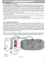
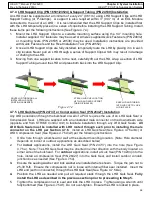
ATTACH TO VERTICAL
SURFACE USING THESE
MOUNTING HOLES (4)
Figure 4.1a
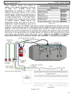
Figure 4.1b
SECURE CYLINDER TO BRACKET
USING 2 STRAPS PROVIDED
CYLINDER BRACKET
CYLINDER
BRACKET

