51
HELIX™ Manual
(P/N 26291)
Chapter 4: System Installation
Rev A (February 2018)
HELIX™ PCU
Fire Suppression System
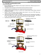
4.3.2 Pneumatic Control Head (P/N 10147
-
R)
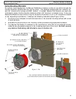
Install per the following:
1.
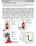
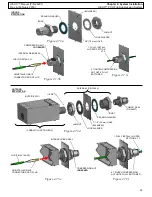
Remove Shipping Plate (P/N 10099) from top of Agent Cylinder Valve. Retain the (2) 5/16”
-
18
bolts (See Figure 2.1a).
2.
Verify piston is fully recessed into Pneumatic Control Head body as shown.
3.
Locate Pneumatic Control Head on top of Agent Cylinder Valve as shown.
4.
Install (2) bolts retained from Step 1 as shown. Use medium grade thread locking compound
and torque to 10 ft
-
lbs.
5.
Install 1/4” NPT Pneumatic Actuation Network (See Section 3.5.2). Use PTFE thread tape.
Tighten a minimum of two turns past hand tight.
6.
Install Vent Check (P/N 10173
-
R). For multiple Control Heads, each Control Head is installed in
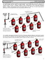
series (See Figure 4.3.2b), and a Vent Check is required at the last Control Head. (See Figure
4.3.2a). Use PTFE thread tape. Tighten a minimum of two turns past hand tight.
7.
Install Dust Cap (P/N 13761) on Vent Check.
PNEUMATIC ACTUATION
NETWORK
(2) 5/16”
-
18 BOLTS
VENT CHECK
(P/N 10173
-
R)
PNEUMATIC CONTROL HEAD
(P/N 10147
-
R)
Figure 4.3.2a
DUST CAP
(P/N 13761)
PISTON
(FULLY RECESSED)
PNEUMATIC ACTUATION
NETWORK
(2) 5/16”
-
18 BOLTS
PNEUMATIC CONTROL HEAD
(P/N 10147
-
R)
Figure 4.3.2b
PISTON
(FULLY RECESSED)
PNEUMATIC ACTUATION
NETWORK

