53
HELIX™ Manual
(P/N 26291)
Chapter 4: System Installation
Rev A (February 2018)
HELIX™ PCU
Fire Suppression System
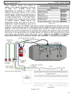
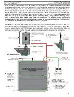
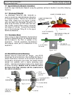
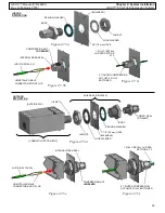
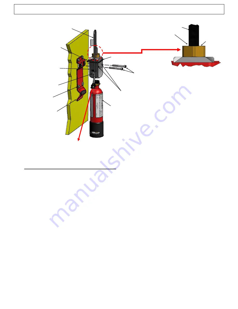
ELECTRIC NITROGEN
ACTUATOR (P/N 20775
-
R)
LINEAR ACTUATOR
(P/N 20500
-
R)
CABLE TIE
(4) 1/4” GRADE 8 BOLTS
NITROGEN CYLINDER
(P/N 09956
-
R)
NITROGEN OUTLET PORT
MOUNTING HOLES
INDOOR ACTUATOR
BRACKET (P/N 10355
-
R)
Figure 4.5
(2) MOUNTING
SCREWS (P/N 10573)
TAMPER SEAL
(P/N 01387)
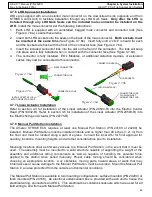
4.6 Pneumatic Actuation Network Installation
Following installation of any Pneumatic Control Heads and Electric Nitrogen Actuators, install the
Pneumatic Actuation Network using the guidelines defined in Section 3.5.2.
After the Pneumatic
Actuation Network is complete and assembled, test the network per instructions in Section
6.2.8 for functionality.
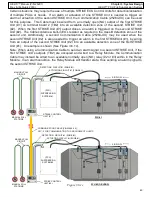
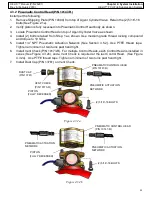
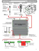
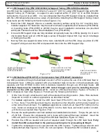
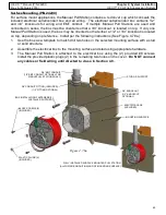
ACTUATION LEAD CABLE
(TO STRIKE UNIT)
(ACTUATOR
ADAPTER)
(LINEAR ACTUATOR)
LINEAR ACTUATOR MUST BE
FULLY SEATED TO BRASS
ADAPTER SURFACE

