55
HELIX™ Manual
(P/N 26291)
Chapter 4: System Installation
Rev A (February 2018)
HELIX™ PCU
Fire Suppression System
Consider the most convenient wire routing path of all external devices when determining the best
mounting
location for the STRIKE Control Unit and enclosure. Electrical knockouts (3/4”) are
provided on the top, bottom, right side and back of the enclosure, which are used for all field wiring
entering the enclosure. Install the STRIKE Control Unit per the following instructions:
1.
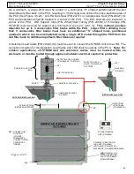
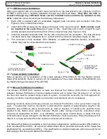
The STRIKE Control Unit enclosure contains (4) mounting holes as detailed in Figure 4.7.2a.
2.
Use the dimensions shown in Figure 2.7.1b or use the enclosure as a template to mark, then
drill the top two holes in the selected mounting surface.
3.
Loosely assemble the enclosure to the mounting surface using appropriate hardware (#10
fasteners are recommended). Level the enclosure and match drill the remaining two lower
holes.
4.
Finish the installation by securely attaching the enclosure using appropriate hardware (See
Figure 4.7.2b).
Do NOT connect any batteries or field wiring to the STRIKE Control Unit
until directed to do so in Section 4.9 and 4.10.
Figure 4.7.2b
UPPER MOUNTING FASTENERS (2)
(INSTALLER SUPPLIED)
MOUNTING HOLE (#10 FASTENER RECOMMENDED)
LOWER MOUNTING FASTENERS (2)
(INSTALLER SUPPLIED)
MOUNTING
SURFACE
ENCLOSURE
Figure 4.7.2a

