60
HELIX™ Manual
(P/N 26291)
Chapter 4: System Installation
Rev A (February 2018)
HELIX™ PCU
Fire Suppression System
4.7.6 LHD Connector Installation
LHDs are supplied with an uninstalled male connector on the downstream side (opposite end from
STRIKE Control Unit) to facilitate installation through any LHD Quik Seals.
Only after the LHD is
installed through
any LHD Quik Seals can the included male connector be installed on the
LHD.
Install the male connector per the following instructions:
1.
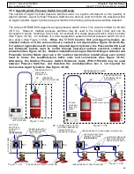
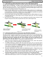
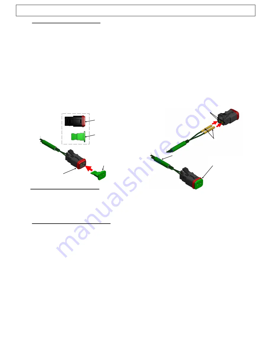
Each LHD is supplied with an uninstalled, bagged male connector and connector lock (See
Figure 4.7.6a). Locate these items.
2.
Insert both LHD sockets into the seals on the back of the male connector.
Both sockets must
be inserted at the same time
(See Figure 4.7.6b). Insert fully until a “click” is heard for each
and the sockets are flush with the front of the connector face (See Figure 4.7.6c).
3.
Insert the included connector lock into the slot on the front of the connector. The lock will snap
into place and is fully installed when in contact with the connector face (See Figure 4.7.6d).
4.
The connector is fully installed. EOL Modules, or additional detection devices, or extension
cables may now be connected to this connector.
Figure 4.7.6c
CONNECTOR LOCK
BOTH SOCKETS FLUSH
WITH CONNECTOR FACE
MALE CONNECTOR
CONNECTOR LOCK
LHD SOCKETS
CONNECTOR SEALS
CONNECTOR LOCK
FLUSH AGAINST
CONNECTOR FACE
Figure 4.7.6a
Figure 4.7.6b
Figure 4.7.6d
LHD (P/N 24744
-
XX)
4.7.7 Linear Actuator Installation
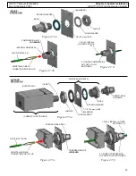
Refer to section 4.3 for installation of the Linear Actuator (P/N 20500
-
R) into the Electric Control
Head (P/N 14032
-
R). Refer to section 4.5 for installation of the Linear Actuator (P/N 20500
-
R) into
the Electric Nitrogen Actuator (P/N 20775
-
R).
4.7.8 Manual Pull Station Installation
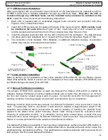
The Amerex STRIKE ECS requires at least one Manual Pull Station (P/N 24168 or 24290) be
installed. Manual Pull Stations must be installed indoors and no higher than 48 inches (1.21 m) from
the floor and must be located along a path of egress. Consult the local AHJ for final approval for
quantity, locations, mounting heights, and all other considerations prior to installation.
Mounting locations shall permit easy access to a Manual Pull Station in the event that it must be
used. The assembly must be mounted to a solid structure capable of supporting the weight of the
assembly and additional wiring components as well as capable of handling the potential force
applied to the station when pulled manually. Proper cable routing should be considered when
choosing an appropriate location. Any obstacles, moving parts, hazard areas, or walls that may
inhibit access or cause damage to the Manual Pull Station must be avoided. Mount the Manual Pull
Station in an area protected from the outside environmental conditions.
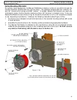
The Manual Pull Station is available in two mounting configurations: surface mounted (P/N 24290) or
flush mounted (P/N 24168). An electrical outlet/conduit box is provided with each unit to house the
electrical wiring, connectors and EOL. This electrical box contains knockouts which are used for all
field wiring to and from each Manual Pull Station.

