62
HELIX™ Manual
(P/N 26291)
Chapter 4: System Installation
Rev A (February 2018)
HELIX™ PCU
Fire Suppression System
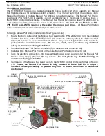
Flush Mounting (P/N 24168)
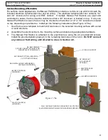
For flush mount applications, the Manual Pull Station contains an oversize red cover plate which
conceals a cutout in the mounting surface used to recess the included electrical outlet/conduit box
and all wiring. Flush mounting requires the electrical box to be attached to a stud or solid structure.
The electrical box contains 1/2” and 3/4” knockouts on the sides and back, either of which can be
used for wiring or EMT conduit if desired. If multiple Manual Pull Stations are used and to be
connected in series, a 3/4” knockout must be used. If only one Manual Pull Station is used, either a
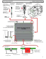
1/2” or 3/4” knockout will suffice. Install per the following instructions (See Figure 4.7.8b):
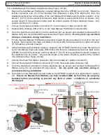
1.
If walls are installed, use the box as a template to cut out a hole in the mounting surface or
wall, directly adjacent to a stud.
2.
Drill two mounting holes (approx. Ø 5/32”) in the side of the box that will attach to the stud.
3.
Mount the box to the stud using appropriate hardware so that the front edge of the box is flush
with the mounting surface.
4.
The Manual Pull Station is attached to the electrical box using the (2) provided #8 screws.
Install the provided plastic plugs (2) in the remaining two holes on the cover.
Do NOT connect
any cables or field wiring until directed to do so in Section 4.9.
Figure 4.7.8b
MOUNTING SURFACE
BOX INSTALLATION
FASTENERS (2)
(INSTALLER SUPPLIED)
STUD OR SUPPORT
#8 CAP SCREWS (2)
(INCLUDED)
PLASTIC PLUGS (2)
(INCLUDED)
1/2” OR 3/4” KNOCKOUTS
AVAILABLE FOR WIRING
CUTOUT FOR BOX IN
MOUNTING SURFACE
DRILL (2) MOUNTING HOLES IN
ELECTRICAL BOX FOR STUD/
SUPPORT MOUNTING
ELECTRICAL BOX
(INCLUDED)
FULLY INSTALLED FLUSH MOUNTED PULL STATION
(ALL WIRING/CONDUIT CONCEALED BEHIND MOUNTING SURFACE)


