64
HELIX™ Manual
(P/N 26291)
Chapter 4: System Installation
Rev A (February 2018)
HELIX™ PCU
Fire Suppression System
Optional Device Installation
Installation instructions for the following Amerex supplied devices are supplied with each device.
Reference the included instructions for installation procedures:
•
Electric Gas Valves (P/N 12870 thru 12876)
•
Horn/Strobe (P/N 21396)
For other optional devices including FACPs not provided by Amerex, reference the manufacturers
installation instructions.
Do NOT connect any field wiring to any installed optional devices until
directed to do so in Section 4.9.
4.8 Field Wiring
Field wiring for the STRIKE ECS may be performed following the installation of the STRIKE Control
Unit enclosure along with all other detection, manual release, actuation, pressure switch, and
optional devices.
Amerex supplied wiring cables must be used for connection of each
detection, manual pull, actuation, and pressure switch circuit back to the
STRIKE
Control
Unit enclosure.
Optional devices, such as Relay Modules, FACPs, gas valves, and external
alarms/signaling devices require installer supplied wiring. Always contact the local AHJ for a
proposed wiring installation. All installations must follow NFPA 70 (National Electric Code) and all
state and local codes. Traditional wiring support methods or EMT conduit may be used as required.
The following subsections describe the available cables and wiring methods for routing each circuit
from each device to and into the STRIKE Control Unit enclosure.
Amerex recommends routing
individual cables by starting at each device and routing the blunt cut end (no connector) of
each “Lead” cable back into the
STRIKE
Control Unit enclosure.
The STRIKE Control Unit
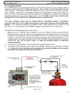
enclosure contains 13 electrical knockouts (3/4”) available for use for all field wiring entering the
enclosure (See Figure 2.7.1a/2.7.1b). Typical installations utilize many cables that require the use
of several of these knockouts. Traditional cable clamps, connectors, or conduit may be used as
required for cable entry into the enclosure. Always contact the local AHJ for a proposed wiring
installation.
Termination of each circuit to the
STRIKE
Control Unit is described later in
Section 4.9.


