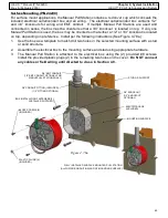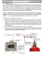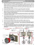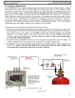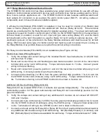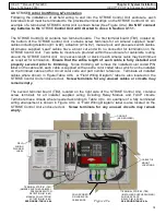
69
HELIX™ Manual
(P/N 26291)
Chapter 4: System Installation
Rev A (February 2018)
HELIX™ PCU
Fire Suppression System
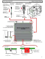
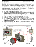
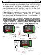
For multiple Manual Pull Station installations (See Figure 4.8.3b):
1.
Begin at the last Manual Pull Station, located farthest from the STRIKE Control Unit. Route the
female connector end (F) of the Manual Pull Extension Cable (P/N 24413
-
XX) from the
installed electrical box to the inside of the next Manual Pull Station electrical box location. Only
about 5” [127.0] of the electrical connectors shall remain in each electrical box as shown. Any
excess length in the extension cable must be stored outside of these electrical boxes. Any
conduit must be 3/4” conduit.
2.
Connect the female pull station connector (F) to the male ext. cable connector (M).
3.
Install an EOL Module (P/N 23474) on the male Manual Pull Station connector (M).
4.
Tuck the electrical connections into the electrical box as shown and reinstall the Manual Pull
Station using the (2) provided #8 cap screws (See Figure 4.9.3a).
Do not pinch any electrical
wiring or connectors during installation
.
5.
If more than two Manual Pull Stations are used, repeat the previous steps (1,2 & 4) for the next
in series, then connect the male pull station connector (M) to the previous ext. cable connector
(F). Otherwise, proceed to step 6.
6.
At the first Manual Pull Station location, closest to the STRIKE Control Unit, route the blunt cut
end of the Manual Pull Lead Cable (P/N 24412
-
XX) from the installed electrical box back to the
STRIKE Control Unit enclosure until only about 5” [127.0] of the electrical connector remains in
the electrical box as shown. Any excess length in the cable should be pulled to the Control
Unit enclosure (See Figure 4.9.3a).
7.
Connect the male Pull Station connector (M) to the female ext. cable connector (F).
8.
Connect the female Pull Station connector (F) to the male lead cable connector (M).
9.
Tuck the electrical connections into the electrical box as shown and reinstall the Manual Pull
Station using the (2) provided #8 cap screws.
Do not pinch any electrical wiring or
connectors during installation.
10.
Termination of the Manual Pull Lead Cable to the STRIKE Control Unit is performed in Section
4.9.
Ensure all Manual Pull Stations are fully installed AND all Pull Pins are properly
installed before proceeding to prevent any fault or alarm conditions or accidental
discharges!
EOL
(P/N
23474)
MANUAL PULL LEAD
CABLE
(P/N 24412
-
XX)
INTO STRIKE CONTROL UNIT
ENCLOSURE
SEE FIGURE 4.8.3a
LEAD & EXTENSION
CONNECTIONS
Figure 4.8.3b
PULL PIN
LEAD & EXTENSION
CABLES
MANUAL PULL EXTENSION CABLE
(P/N 24413
-
XX)
MANUAL
PULL
STATIONS
(F)
ROUTING DIRECTION
(M)
CONNECT
CONDUIT
(AS REQ.)
5” [
127.0]
APPROX.
(M)
ELECTRICAL BOX
CONDUIT (AS
REQUIRED)
(F)
(M)
(F)
(M)
ELECTRICAL BOX
ROUTING
CONNECT
CONNECT
#8 CAP
SCREWS
5
” [127.0]
APPROX
.
S
E
E
F
IGURE
4
.9
.3
a


