70
HELIX™ Manual
(P/N 26291)
Chapter 4: System Installation
Rev A (February 2018)
HELIX™ PCU
Fire Suppression System
4.8.4 Pressure Switch Circuit
The STRIKE ECS has a single dedicated pressure switch circuit which supports Agent Cylinder
Pressure Switches used with the Amerex HELIX Fire Suppression System. The pressure switch
circuit forms a continuous, normally closed loop and may utilize a single or multiple pressure switch
devices connected in series. The Pressure Switch Lead Cable (P/N 24414
-
XX) is used to connect a
single device, or first device in a series, back to the STRIKE Control Unit enclosure. The Pressure
Switch Extension Cable (P/N 24703
-
XX or 21539
-
XX) is used between devices connected in series
on the same circuit. All pressure switch cables and components are color coded blue for reference.
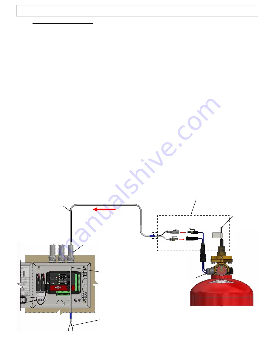
The single pressure switch circuit is routed from the STRIKE Control Unit enclosure to the Agent
Cylinder(s). 3/4” electrical knockouts are provided on the STRIKE Enclosure. This circuit may be
routed through the same EMT conduit as the actuation circuit if desired.
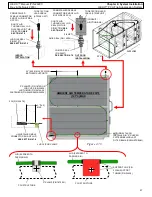
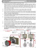
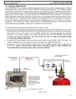
For single pressure switch circuit installations (See Figure 4.8.4a):
1.
Beginning at the installed Pressure Switch on the Agent Cylinder, route the blunt cut end of the
Pressure Switch Lead Cable (P/N 24414
-
XX) from the Agent Cylinder or junction box (if required,
See Section 3.6.5) to the inside of the STRIKE Control Unit enclosure through the selected
knockout. Any excess length in the cable should be pulled into the STRIKE Control Unit
enclosure and may be trimmed later.
Do not cut, pinch, crush, or chafe any electrical wiring
or connectors during installation.
2.
Connect the Pressure Switch connectors to the lead cable connectors [(M) to (F);(F) to (M)]. For
outdoor installations, this connection should be housed in an outdoor junction box.
3.
Termination of the Pressure Switch Lead Cable to the STRIKE Control Unit is performed in
Section 4.9.
Ensure the Pressure Switch and associated cable are fully installed and
connected before proceeding to prevent any fault conditions.
Figure 4.8.4a
PRESSURE SWITCH
LEAD CABLE
(P/N 24414
-
XX)
(LINEAR
ACTUATOR)
STRIKE CONTROL
UNIT
(F)
ROUTING DIRECTION
(M)
PULL LEAD CABLE INTO
STRIKE CONTROL UNIT
ENCLOSURE THROUGH
SELECTED
KNOCKOUT
LOCATION. ANY
EXCESS LENGTH MAY
BE TRIMMED LATER PER
SECTION 4.9.
CONDUIT
(AS REQUIRED)
LEAD CABLE BLUNT CUT END
(F)
(M)
CONNECT x 2
(PRESSURE
SWITCH)
JUNCTION BOX & CONDUIT
(AS REQUIRED)


