72
HELIX™ Manual
(P/N 26291)
Chapter 4: System Installation
Rev A (February 2018)
HELIX™ PCU
Fire Suppression System
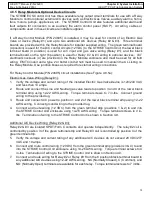
4.8.5 Relay Module & Optional Device Circuits
The STRIKE ECS Control Unit has three available relay output circuit terminals for use with a Relay
Module to control optional external A/C devices such as Electric Gas Valves, auxiliary alarms, horns,
fans, motors, pumps, appliances, etc. The STRIKE Control Unit also features additional alarm and
fault outputs for connection to an auxiliary fire alarm control panel (FACP). All wiring, cables or
components used in these circuits are installer supplied.
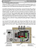
If a Relay Control Module (P/N 24695) is installed, it may be used for control of an Electric Gas
Valve or device (Relay #1) and up to two additional A/C devices (Relay #2 & #3). Three terminal
boards are provided within the Relay Module for installer supplied wiring. The green terminal board
(4 position) is used for the D/C control circuits (12 VDC) to the STRIKE Control Unit; the lower black
terminal board (4 position) is used for A/C input and gas valve wiring (Relay #1); and the black
terminal board on the right (6 position) is used for Relay # 2 & #3 wiring to optional devices. 3/4”
electrical knockouts (4) are provided on the Relay Module enclosure and must be used for all field
wiring. EMT Conduit and a type 2 or better conduit hub must be used to maintain the UL Listing on
the Relay Module. Use junction boxes as required for external wiring connections.
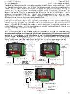
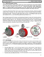
For Relay Control Module (P/N 24695) circuit installations (See Figure 4.8.5a):
Electric Gas Valve Wiring (Relay #1):
1.
Verify the voltage and current rating of the installed Electric Gas Valve/device is 120/240 VAC
and less than 10 amps.
2.
Route and connect the Line and Neutral gas valve leads to position 3 and 4 of the lower black
terminal strip using 12
-
22 AWG wiring. Torque terminal screws to 7 in
-
lbs. Connect ground
wiring to the provided lug.
3.
Route and connect A/C power to position 1 and 2 of the lower black terminal strip using 12
-
22
AWG wiring. Connect ground wiring to the provided lug.
4.
Connect and route wiring (12 VDC) from the green terminal strip (positions 1 & 2) to and into
the STRIKE Control Unit enclosure using 14
-
26 AWG wiring . Torque terminal screws to 4 in
-
lbs. Termination of wiring to the STRIKE Control Unit is shown in Section 4.9.
Additional A/C Device Wiring (Relay #2 & #3):
Relay #2 & #3 are isolated SPDT/Form C contacts and operate independently. The relay #2 coil is
controlled by position 3 of the green terminal strip and Relay #3 coil is controlled by position 4 of the
green terminal strip.
5.
Verify the voltage and current rating of any additional A/C devices do not exceed 28 VDC/277
VAC and 10 amps.
6.
Connect and route control wiring (12 VDC) from the green terminal strip (positions 3 & 4) to and
into the STRIKE Control Unit enclosure using 14
-
26 AWG wiring. Torque terminal screws to 4
in
-
lbs. Termination of wiring to the STRIKE Control Unit is shown in Section 4.9.
7.
Connect and route wiring for Relay #2 or Relay #3 from the 6 position black terminal board to
any additional A/C devices using 12
-
22 AWG wiring. NC (Normally Closed), C (Common), and
NO (Normally Open) terminals are available for each relay. Torque terminal screws to 7 in/lbs.

